
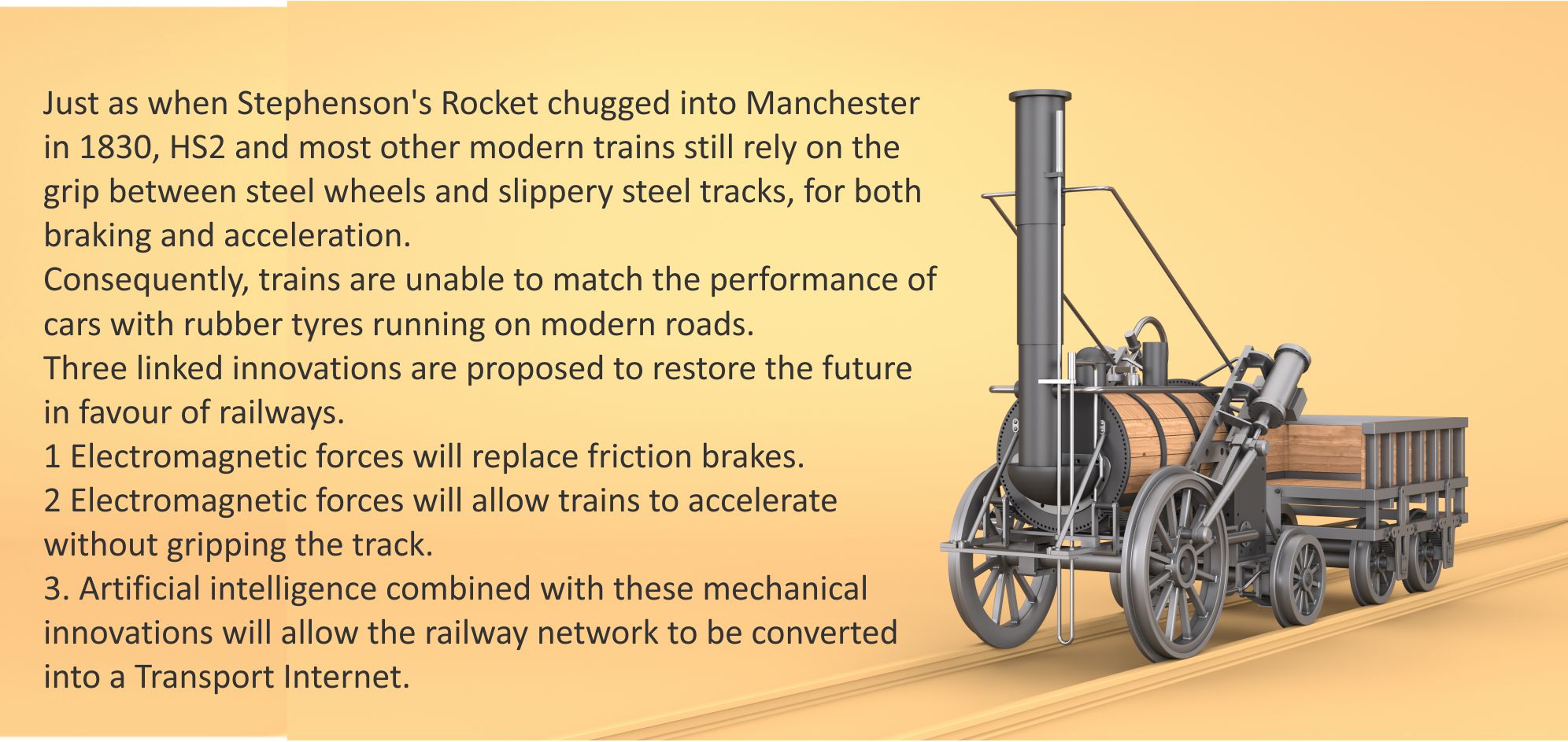
Bill Courtney hopes that this revolution will be born in his native North of England. But his first priority is to protect the Earth’s environment. So, if you live elsewhere on the planet and feel that your national railways could benefit from these innovations, you are encouraged to go ahead and champion them locally.
At the time of writing this article, there are plans to revive the prosperity of the North of England by building new railways into Manchester from Liverpool and Birmingham. However, these plans fail to take into account the threat of self driving cars, they focus on a small fraction of the North and are based on 1830s braking and traction technology.
But there is a far better way of reviving the North and here it is in a nutshell.
Level One description
This level provides the busy reader with sufficient information to make an initial assessment of the innovations.
1.1 Innovation A: Iron Rail eddy current brakes.
Game changing advantage: Reducing emergency stopping distances could double the capacity of the railway network without having to build new lines.
Traditional friction based railway train braking suffers from three disadvantages.
(i) The brake pads, wheels and tracks all suffer wear over time.
(ii) If the brakes are applied too harshly, the wheels just skid along the tracks instead of gripping them.
(iii) Autumn leaves on the track can reduce grip during braking.
In the 1990s, German railway engineers overcame these problems by using contactless eddy current brakes. [Eddy currents are explained at Levels 2 and 3.]
Contactless brakes eliminated friction wear on the wheels and tracks, but created a new problem because the tracks heated up and had a natural tendency to expand. The Germans neutralised this problem by pre-stretching the rails as they were being laid, so that the stretched rails also had a natural tendency to contract.
This solution was only possible because new rails were being laid for the new trains. This strategy worked, but there were limits to how much pre-stretching could be applied.
Our solution is to add an extra pair of iron rails for the eddy current brakes to operate on. These iron rails are laid in short lengths, with an expansion gap between each iron rail along the chain.
With Innovation B in mind, these new rails need to have a ‘U’ shape.
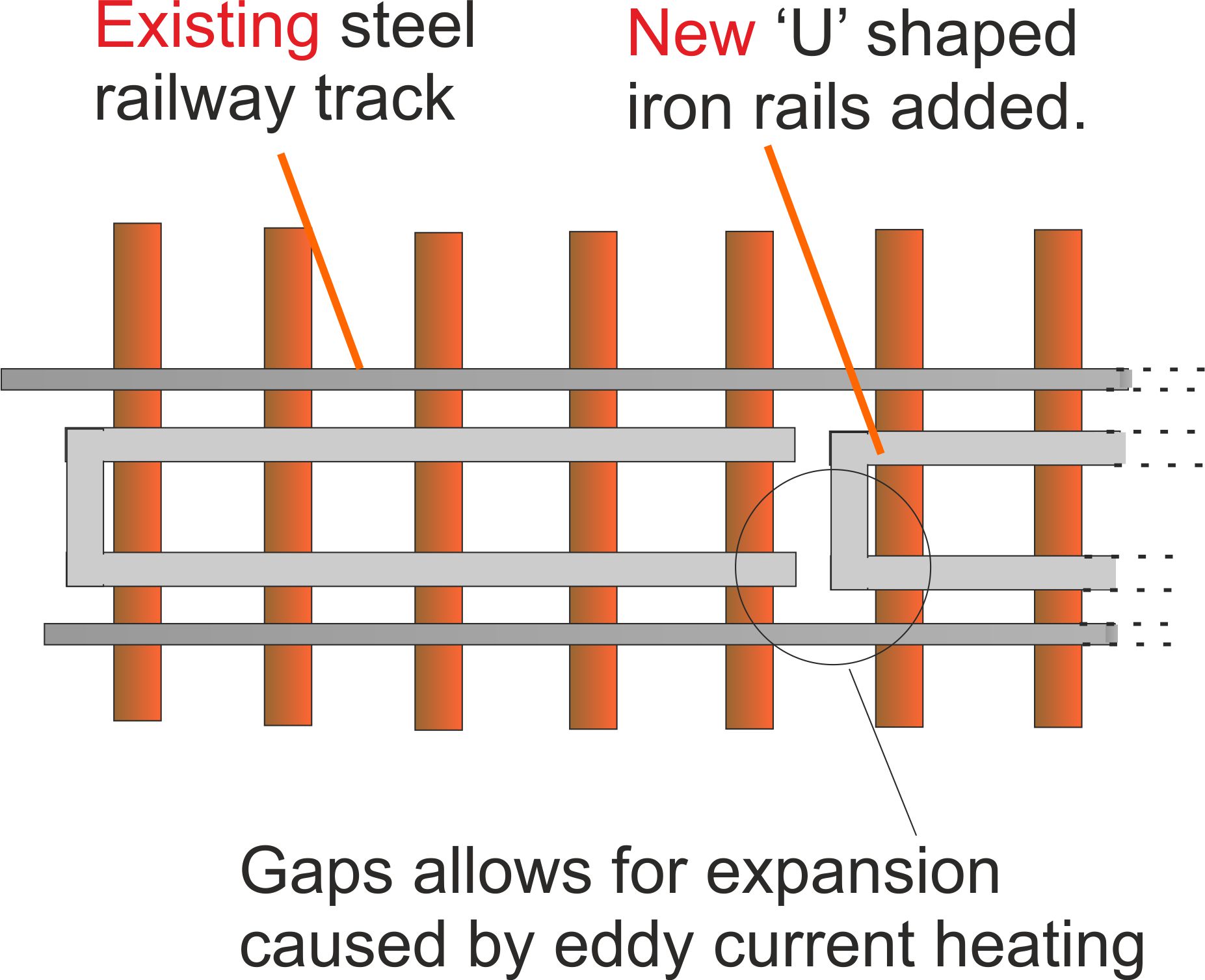
Figure 1. Leaving expansion gaps in the steel rails was not an option for the German engineers because this would create a rough ride and limit the top speed of the trains.
The ‘U’ shape is not necessary for eddy current braking, but plays a vital role in the next innovation.
As will be explained later, iron rail eddy current brakes are at least an order of magnitude more powerful than their steel rail equivalents. This will allow emergency stopping distances to be considerably reduced, making the goal of at least doubling the capacity of the network a reasonable one to achieve.
1.2 Innovation B: Iron Rail Maglev
Game changing advantage: By eliminating reliance on the poor grip between steel wheels and a steel track, acceleration could be improved and higher top speeds achieved.
The primary aim of Iron Rail Maglev is to create a new generation of trains that offer better acceleration than conventional high speed trains, with the levitation or floating feature being treated as a bonus.
Existing Maglev trains hover on a magnetic cushion instead of running on wheels. This means that they also have to rely on a new form of traction that does not depend on train wheels gripping the track.
In Britain, we claim that Professor Laithwaite invented Maglev in 1964, but other nations beg to differ.
After reading Professor Laithwaite’s 1977 book, ‘Propulsion without Wheels’ Bill Courtney became interested in Laithwaite’s train propulsion technology.
But, he has little interest in the levitating features of Maglev, because he believed that its technical benefits were over-sold.
However, Iron Rail Maglev does exploit the levitating forces by using them to create a new type of tilting train that enables trains to travel round bends at higher speeds.
1.3 Innovation C: Employing AI to create a Transport Internet
Game changing advantage: By using artificial intelligence to plan one-off train journeys, we can use the network more efficiently and make the railways more profitable.
The basic concept behind the Transport Internet is almost as old as the railways themselves. For example, many one-off train services were provided to allow visitors from all parts of the UK to visit The Great Exhibition in London in1851.
Outline
Iron Rail eddy current brakes will significantly increase the capacity of the network, but during off-peak periods, this extra line space will be underused. However, by taking advantage of recent developments in driverless trains, artificial intelligence (AI), cellular communications and GPS, we could use this off-peak railway line space to create a transport internet.
A modest level of bespoke railway journeys for goods and people are already on offer, with the proposed Transport Internet being a logical expansion that can cope with far more complex bespoke demands.
1.4 A summary of innovations A, B and C
A common feature of all these innovations is that they are based on modifying the existing network. So the time and cost of adding entirely new lines would be saved.
|
Innovation |
Purpose |
Timescale |
Requirements |
|
A: Iron Rail Eddy current brakes |
To at least double the capacity of the existing railway network by reducing emergency train stopping distances. |
Trains with improved brakes running on busy intercity lines within 8-10 years, with local lines being upgrade within 10 -15 years. |
Braking electromagnets will need to be fitted to existing rolling stock and additional iron rails added in parallel with the existing steel tracks. |
|
B: Iron Rail Maglev |
To reduce travel times by using a form of propulsion that does not rely on grip between the train wheels and the track. |
Ambitious nations could be using Innovation B a year or so after delivering Innovation A. |
New rolling stock fitted with a more complex design of electromagnet compared with Innovation A will be required. |
|
C: A Transport internet |
To compete with driverless road transport by moving goods and passengers more flexibly than fixed timetables allow. |
A very limited version already exists, but for maximum traffic density, Innovation A need to be implemented first. |
In order to maximize the potential of the Transport Internet, driverless single carriage trains will be required. |
|
We can have a very high level of confidence in the futures of Innovations A and C because they are extensions of existing technology. There is less certainty about Innovation B because it is so novel. Fortunately, Innovations A and C are the most important if we want to revolutionize the railways so that they can remain competitive in the age of self-driving road vehicle. |
|||
Unlike many green revolution technologies that rely on scarce minerals, the ‘wonder material’ that makes all of these innovations possible is iron. So, in one sense, in creating a new greener transport system, we will be entering a new Iron Age.
[Building a new green future based on lithium and other minerals that are unevenly distributed in the Earth’s crust could make democratic countries dependent on authoritarian states for their prosperity.]
1.5 Rethinking our railway plans for the North of England
Current plans for modernizing the North of England railway network include,
(i) Building a slimmed down version of HS2 that will ‘Deliver 85% of the benefits for 60-75% of the cost’. [Figures quoted from a letter to the government from Northern Powerhouse business leaders, 14 October 2024.]
(ii) Building a new railway line between Liverpool and Manchester for around £17 billion.
These are exciting plans if you live and work close to the centre of Liverpool, Manchester or Birmingham.
But if you live anywhere else in the North, you will have to make-do with the trickledown wealth flowing out of these cities.
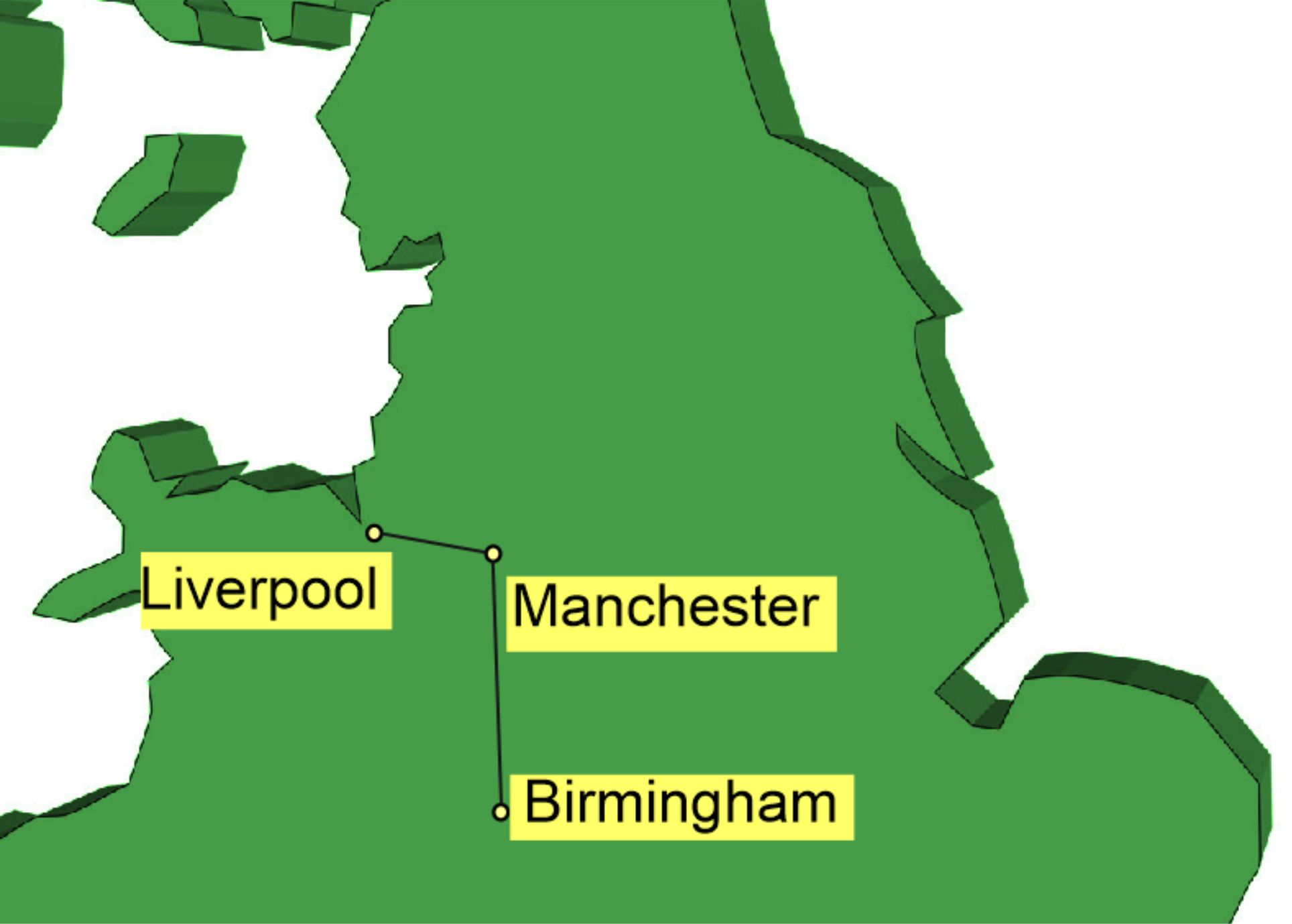
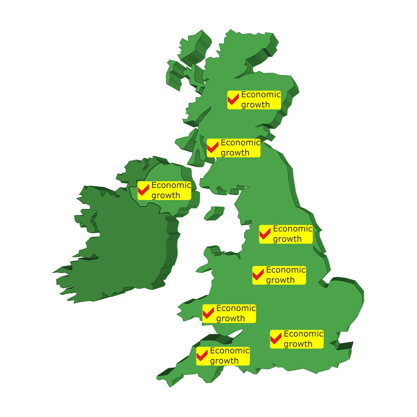
Figure 2. In order to bring prosperity to the wider North, we cannot rely on improved connectivity between just three cities..
A three phase plan for improving connectivity for the whole of the North
For a similar cost to building new lines into Manchester from Birmingham and Liverpool, we could complete Phase One of a new Iron Railway Age and make a good start on Phase Two as well.
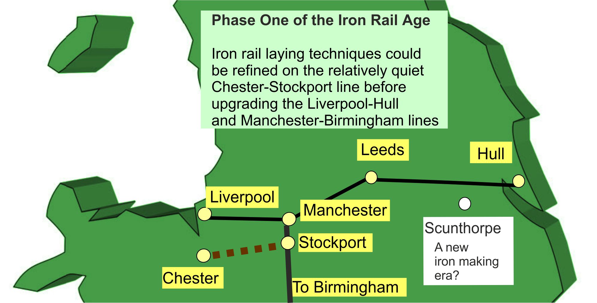
Figure 3. During Phase Two, the revolution could spread north to the main cities on both sides of the Pennines. Then, during Phase Three, the suburban lines would be upgraded so that travelers can get to the main lines faster.
The revolution would spread rapidly to the rest of the UK because the new Iron Rail laying techniques will become standard engineering practice.
1.6 Saving the British iron/steel making industry in Scunthorpe
(And hopefully in Port Talbot too)
The UK has 9,824 miles of railway track. So, we will need a lot of iron, if we want to create a new Iron Rail Age.
But, by the time that the first iron rails are laid down, Britain may have lost its traditional iron making capacity and the rails will have to be imported.
Within the next few years, the blast furnaces in Scunthorpe will need to be replaced by new furnaces that use hydrogen for iron ore reduction to pure iron, if Britain is to meet its climate change commitments.
Bill’s Latent Power Turbines could be used to produce the required hydrogen at very low cost. [Latent Power (LP) Turbines can extract heat from their surrounding atmospheric air and convert it into electricity.]
One option would be for Scunthorpe to be the first town in the UK where each building that consumes electricity would be fitted with its own LP Turbine. During off-peak periods, the surplus electricity that they are capable of producing could be pooled and used to split water into oxygen and hydrogen, with the hydrogen being used for virgin steel/iron production.
****************************************
Level Two description
This level provides more technical information about the innovations
2.1 The self-driving car threat to railways
Self-driving cars will become legal on UK roads from 2026 onwards, but twenty years from now, many drivers may still prefer to be in control of their vehicles on busy city streets.
However, drivers will be far more willing to hand over control of their vehicles to artificial intelligence in the simplified environment of motorways. This will free drivers to do other things, while travelling along motorways.
The car makers will see this as an opportunity to sell more cars by adding new features to make motorway travel time more productive or entertaining. In particular, their innovations will make mobile office work far more productive than doing equivalent work in the public space of a train. .
Motorway traffic jams will often bring a sense of relief because the driver will be able to continue working without the distractions of office life.
Freight haulage will also benefit from ‘driverless’ technology, with lorries travelling along motorways in tight convoys to reduce wind resistance and save fuel.
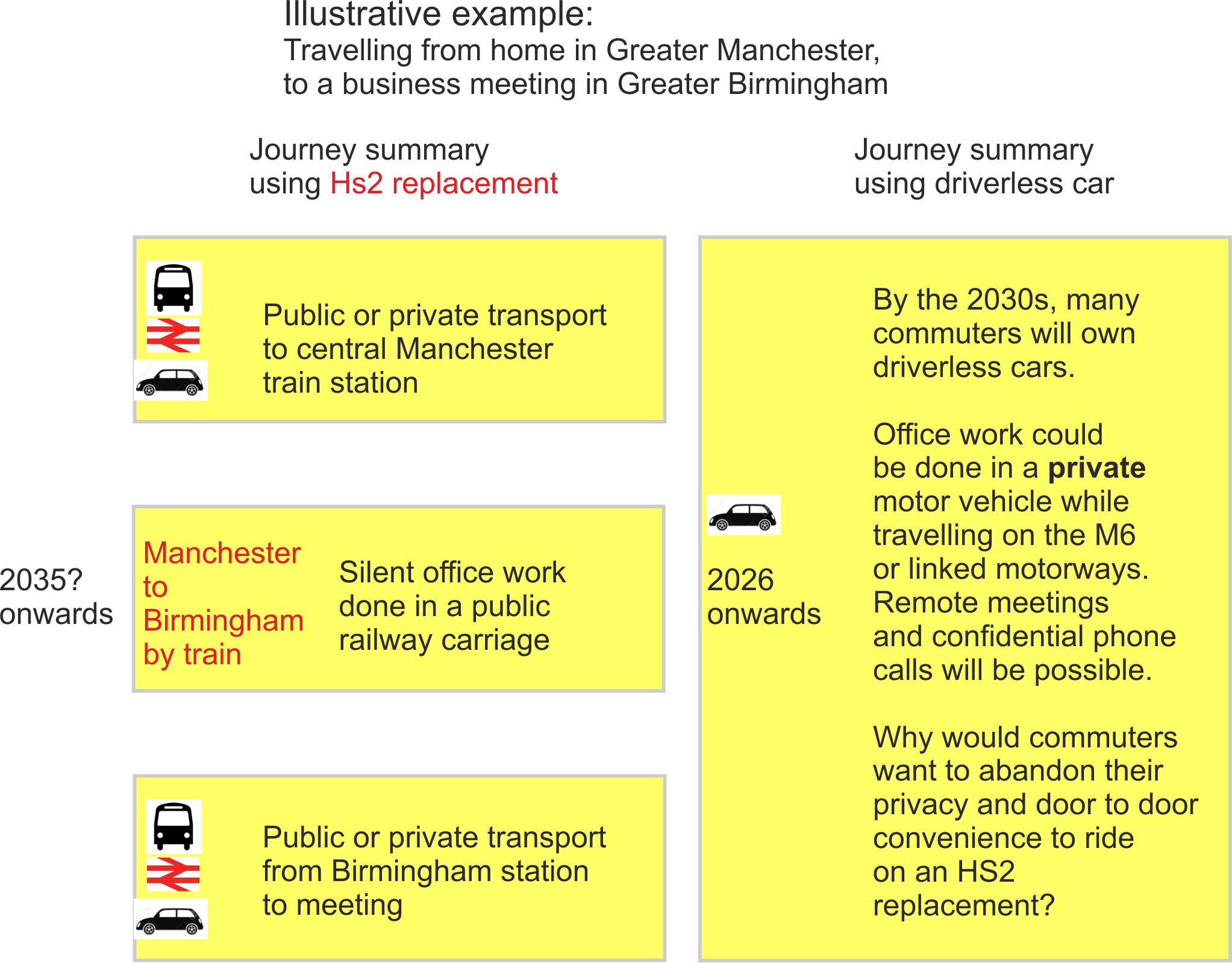
Figure 4. By the time the new railway line between Manchester and Birmingham has been built, it will be solving yesterday’s problems because self driving road vehicles will have made motorway travel a more productive experience.
Increasing the threat: Second generation self-driving vehicles
The current generation of self-driving vehicles are designed to ‘think for them selves’, making decisions in the best interest of the vehicle occupants.
However, once a significant fraction of motorway traffic is travelling in self-driving mode, the traffic will be able to flow more smoothly if a central computer system coordinates the movement of all self-driving vehicles on the motorway at the time. This will allow motorways to carry more traffic than today while reducing journey times and collisions.
The advantages of this synchronised traffic flow will be enjoyed on all public roads, posing an even greater threat to the railway travel alternative.
The big fear relating to all centrally controlled transport units is that cybercriminals will hack into the controls and deliberately induce crashes.
The general principles for dealing with this threat will be discussed at Level Three.
2.2 The rolling stock upgrade required for eddy current braking
As with their German predecessors, electromagnets will be suspended on the underside of the rolling stock, to induce eddy currents in the iron rails.
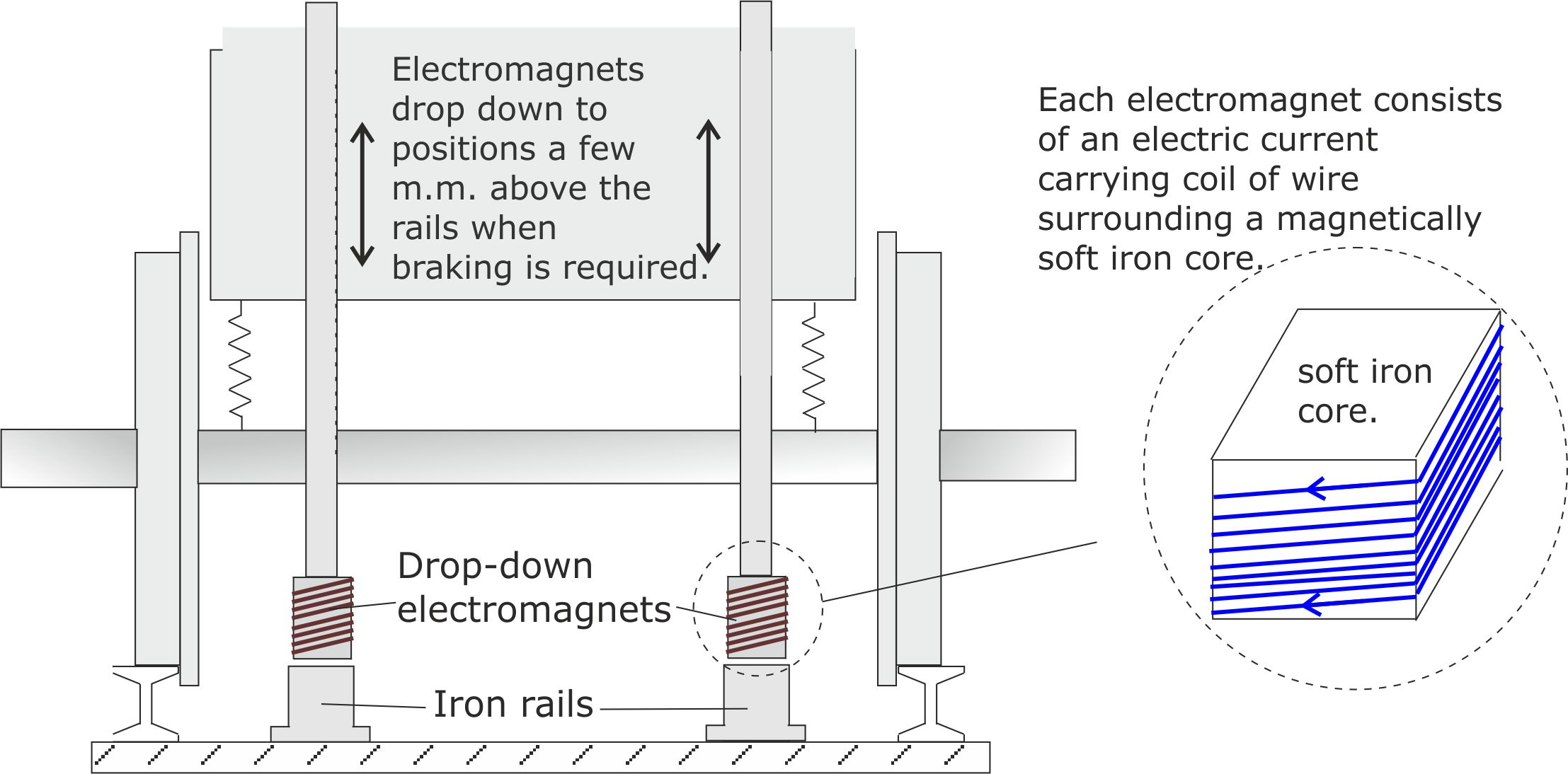
Figure 5. Eddy current brakes are very effective at high speed but they lose braking power at low speeds because the eddy currents are weaker. So, conventional friction brakes are still required for bringing the train to a final halt.
2.3 The Shanghai Maglev
The Shanghai Maglev made history when it became the world’s first commercial Maglev train in 2004.
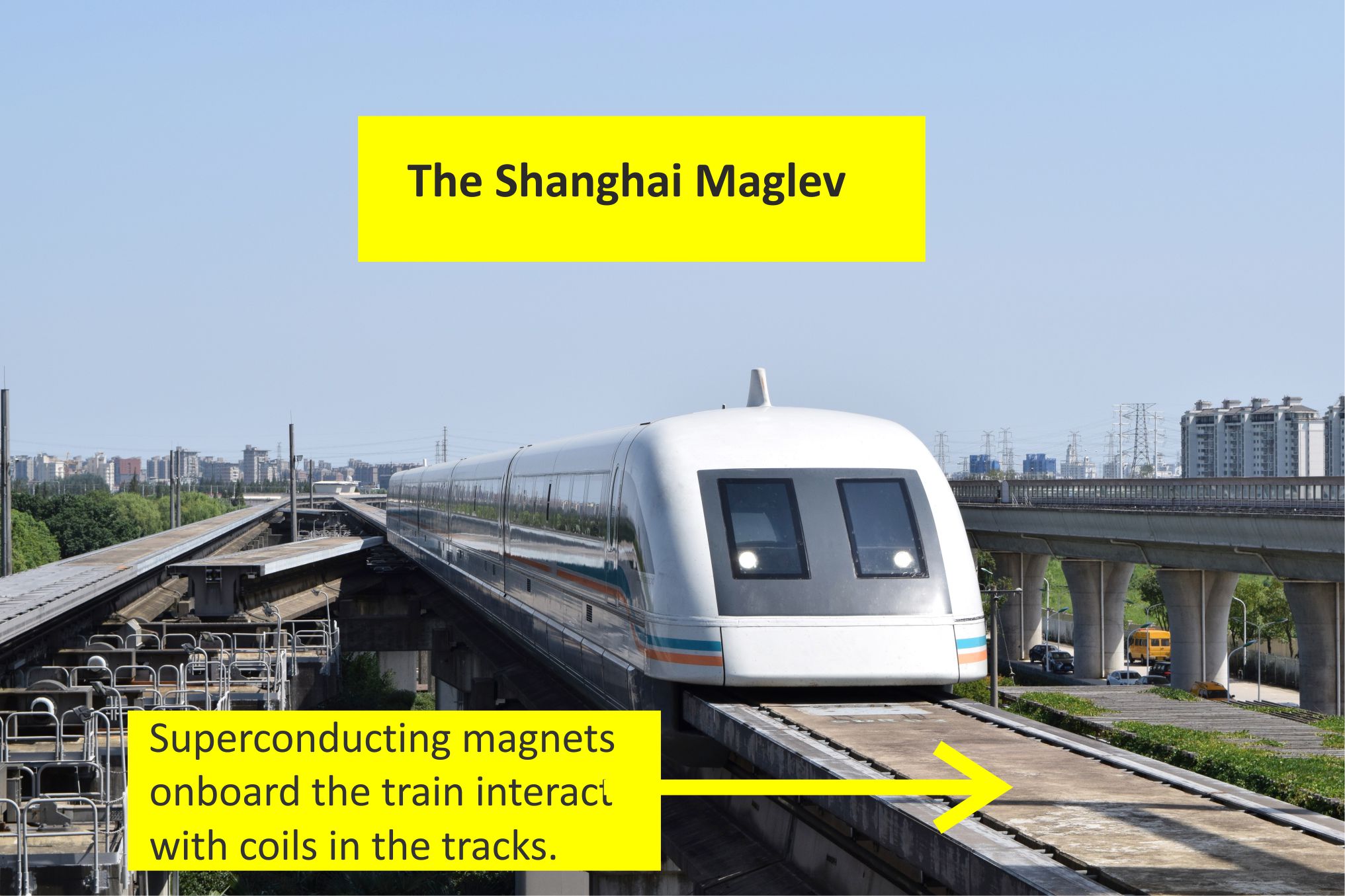
Figure .6 The Shanghai Maglev is famous because it runs at record breaking speeds of up to 288 miles per hour and floats on magnet cushions. But the track is expensive to build and only three countries, China, South Korea and Japan have built Maglev systems to date.
The British competition
Iron Rail Maglev slashes the track laying costs by employing the same iron rails that are used for iron rail eddy current braking.
2.4 Creating the magnetic fields required for Iron Rail Maglev
Iron Rail Maglev trains will induce magnetic fields in the U shaped iron rails as they pass over them.
The following diagrams explain how the onboard electromagnets induce magnet field lines along each arm of the U shaped iron rails.
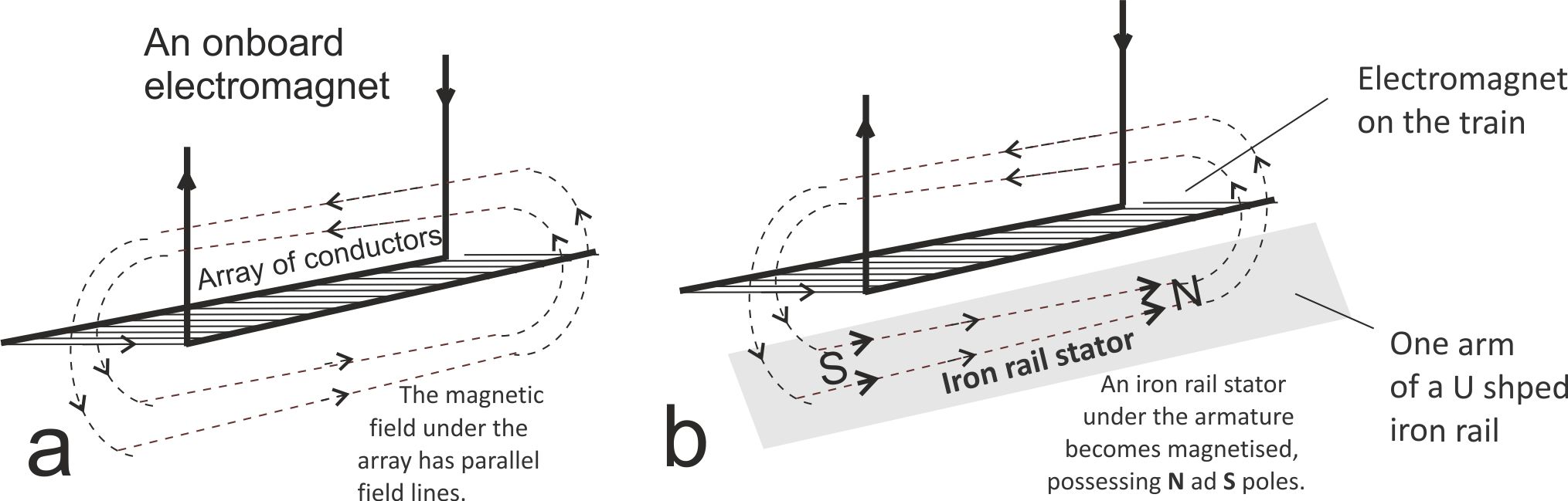
Figure 7. A parallel array of current carrying conductors will produce a magnetic field as shown in a. This can be used to induce a magnetic field in an iron rail as shown in b.
Magnetic field lines are in a state of tension and try to move apart to reduce the tension. Consequently, if the field lines are parallel, as in the above diagram, the array of conductors tries to move away from the iron rail to reduce the tension.
We can use the same tension reduction principles to achieve propulsion because like poles repel and unlike poles attract to reduce tension.
In the following diagram, the two arrays of current carrying conductors are acting as the armatures (i.e., the moving parts) of an electric motor. The armatures induce magnetic fields in the underlying rails, but the rails are stationary, so the armatures move to reduce the tension instead.
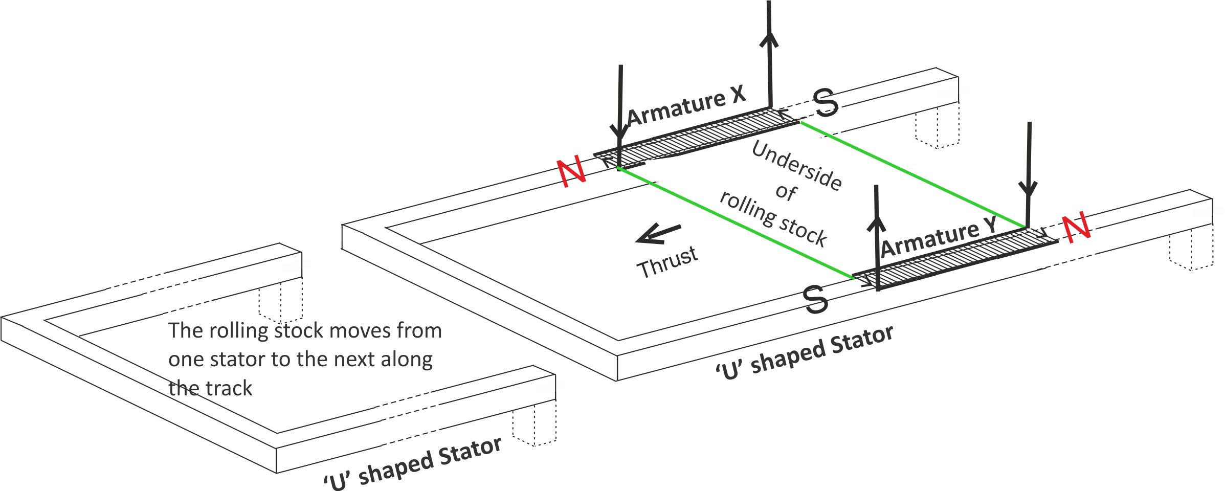
Figure 8. If the current flow in one of the armatures is reversed so that like poles face each other inside the cross member, the direction of thrust will be reversed.
2.5 The weakness of this armature design
Unfortunately, this simple shape of armature is prone to overheating.
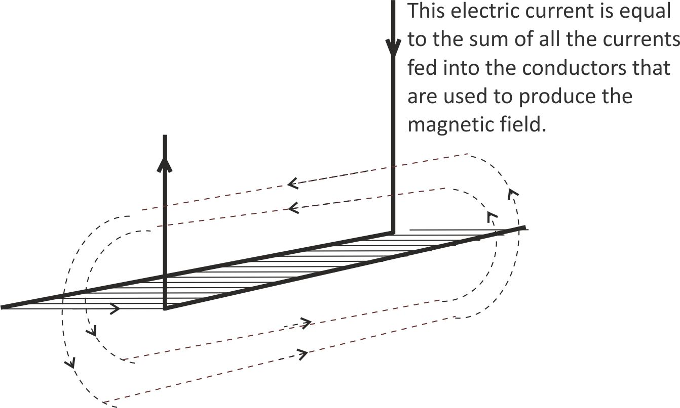
Figure 9. All of the current carrying elements are fed in parallel by the power supply. Consequently, the power supply current will have to be very large, with the I2R heating effect increasing correspondingly.
2.6 Maglev using rectangular shaped armatures
Rectangular box shaped armatures will be bulky, but have the merit of feeing the parallel array of conductors in series.
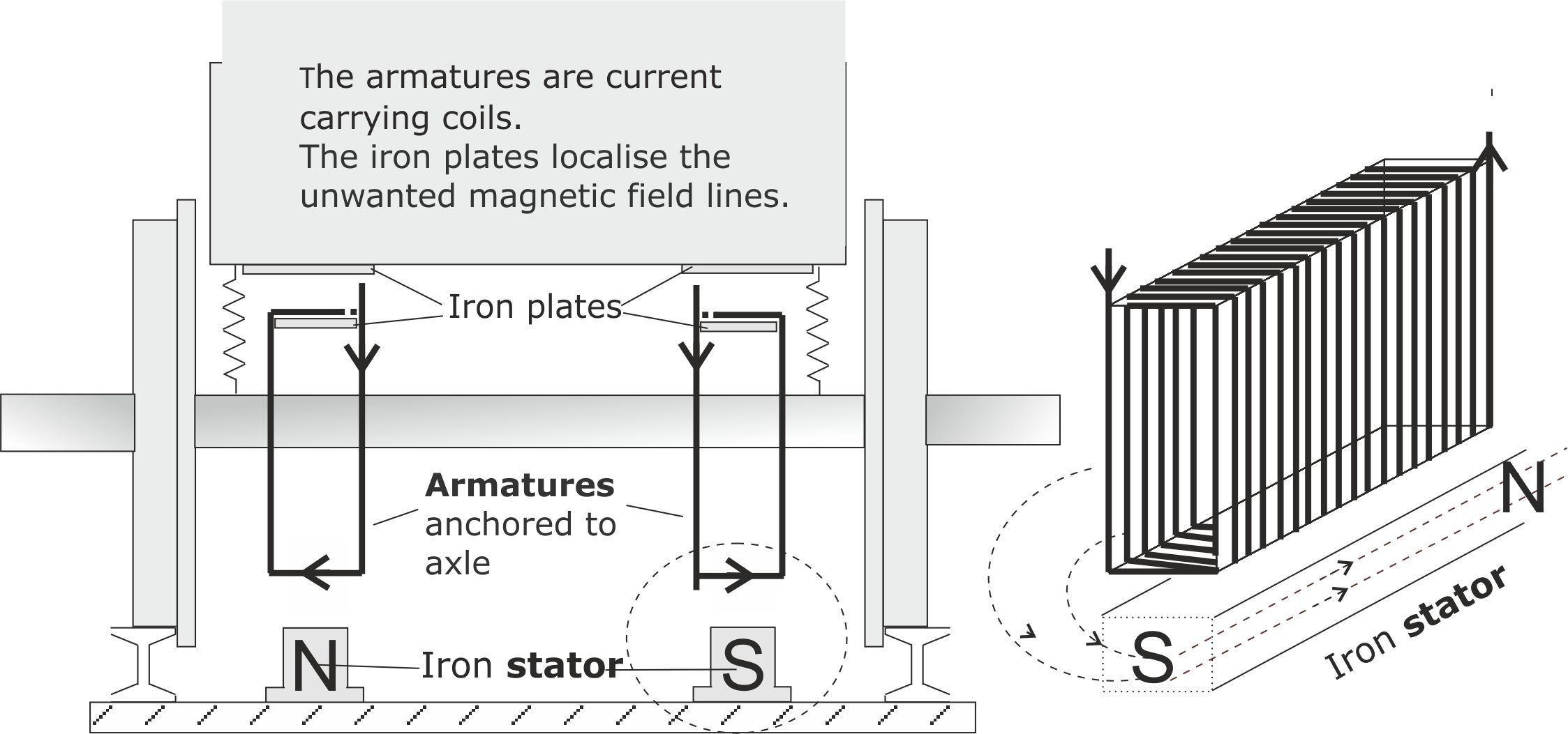
Figure 10. The coils need to be anchored to the wheel axles to hold them at a fixed distance from the track.
2.7 Building an evolving Transport Internet
A very limited form of Transport Internet could be introduced using the existing network and this should be done, with a view to providing a learning experience for both human operators and AI enabled computer stems.
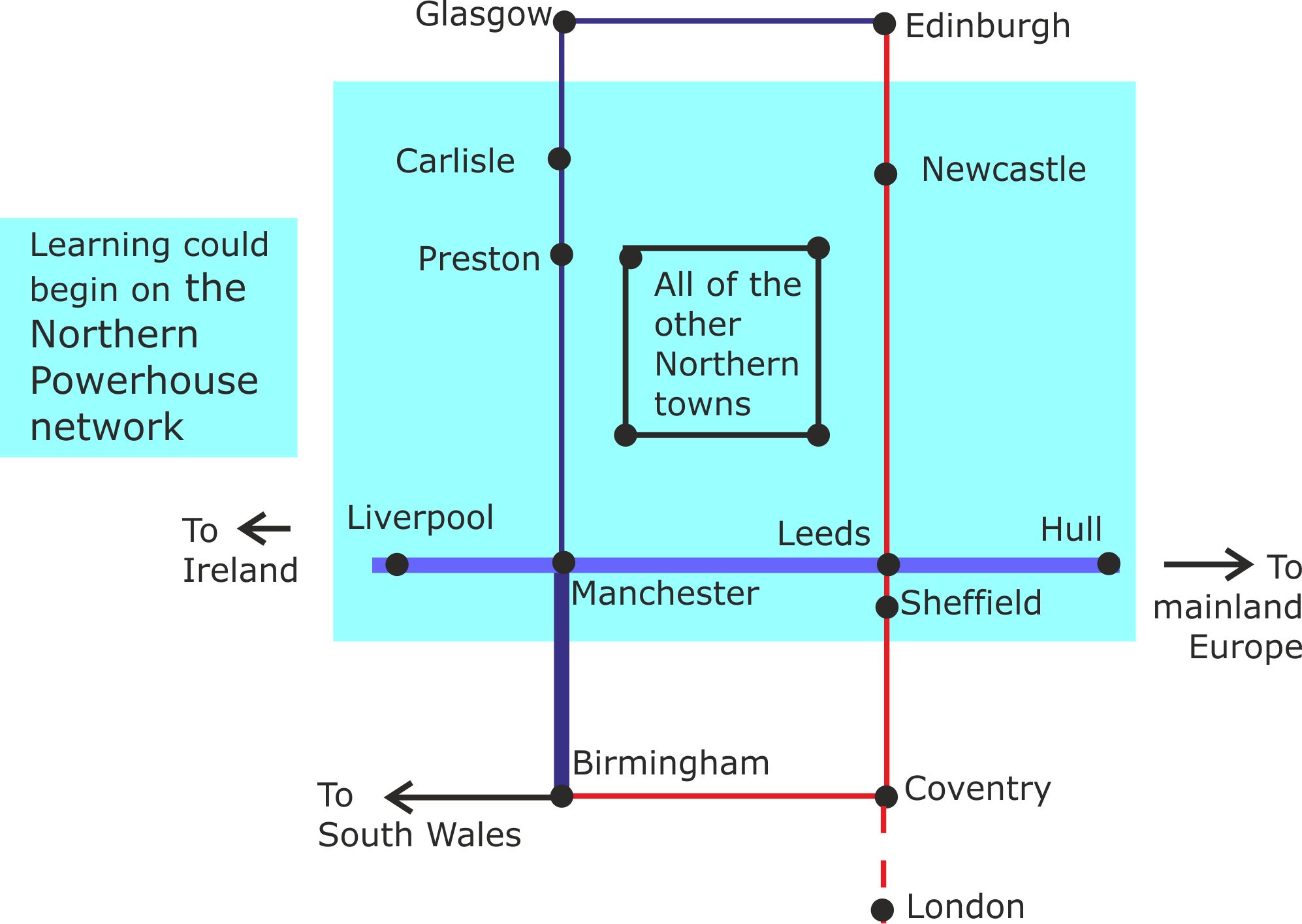
Figure .11. A very limited version of the Transport Internet (TI) could be introduced in the Northern Powerhouse Rail region, with the TI becoming ever more complex as it spreads nationally and factors in the increased capacity offered by Iron Rail technology.
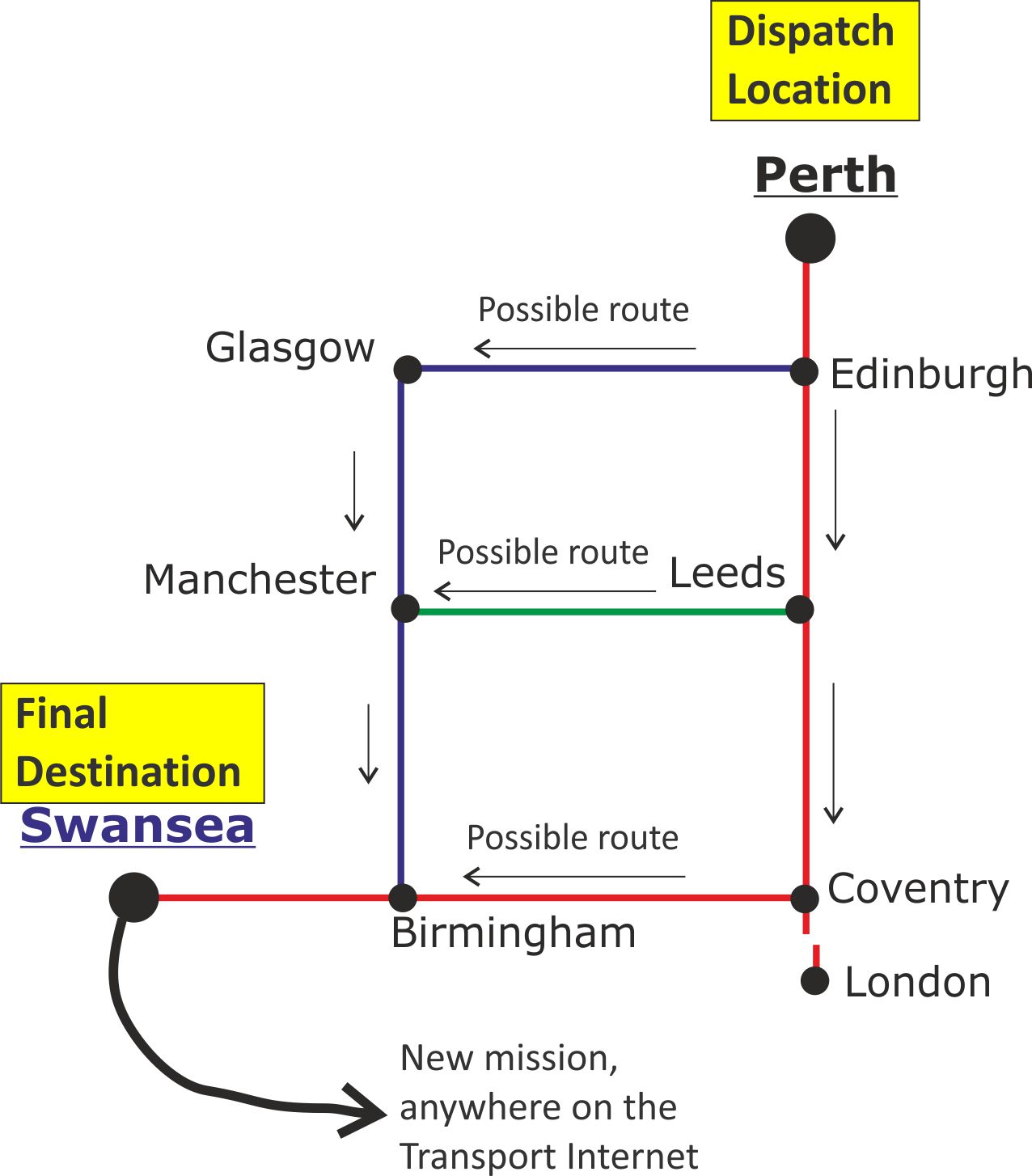
Figure 12. In order to gain the maximum output from the TI, the artificial intelligence will have to take into account a number of route options along the journey. It will also need to ‘think ahead’ to ensure that each unit of rolling stock spends the minimum amount of time travelling empty between jobs.
The ultimate version of the Transport Internet will also include road stages of the journey, taking into account potential traffic holdups along the possible route options.
****************************************
Level Three description
This level addresses some of the issues that may still be puzzling you.
3.1 The friction problem that limits railway development
The capacity of our existing tracks is limited by the low friction grip between steel railway rolling stock wheels and steel rails. Consequently, in order to avoid crashes, very large gaps have to be left between successive trains travelling along the same track. By comparison, modern road vehicle tyres enjoy an excellent grip with dry modern road surfaces.
Figure 13. The reverse problem is experienced when trains are accelerating, because if they try to accelerate too rapidly, the wheels just skid over the rails.
Today’s generation of railway engineers have been trained to accept friction limited acceleration and braking as ‘the facts of railway life’. Consequently, their plans for future improvements are focused on building new straighter lengths of railway track to reduce journey times (with HS2 being a painfully expensive example) and taking drastic action to reduce emergency stopping distances.
Currently, the only way of reducing emergency stopping distances is to sprinkle sand on the tracks.
Research at Network Rail’s Innovation and Development Centre in Melton Mowbray suggest that recent developments in sand spreading techniques can reduce emergency stopping distances by half and significantly reduce train accidents, especially in the vicinity of stations. However, sanding causes abrasion problems because quartz sand is harder than the type of steel used for railway tracks and train wheels. So sanding is only used as a last resort when absolutely necessary.
In contrast, Iron Rail eddy current brakes have the potential to offer shorter stopping distances than sanding and do not cause any abrasion.
Iron Rail eddy current brakes could provide trains with similar stopping distances to road vehicles. However, this would be too abrupt for routine braking of passenger trains because standing passengers would be thrown off their feet. No such restrictions apply to freight trains. So, a future generation of freight trains could have shorter stopping distances than passenger trains. This would be particularly important in a Transport Internet age characterised by many single unit freight trains travelling around the network.
Reducing stopping distance will allow future trains to safely continue moving at high speeds until they are closer to their next stop.
This may only shave a minute or less from journey times between two successive stops, but the effect will be cumulative, with local trains that have many stops along their routes enjoying the largest reductions in journey times.
For example, a local train making ten stops on a 90 minute journey might be able to cut the full journey time down to 80 minutes.
And, if the following generation of local trains use Maglev technology, this could shave another minute off the time between stations. In total, this would reduce today’s total journey time of 90 minutes down to 70 minutes.
High speed through trains using the same track also benefit from this time reduction. Thus, before modification, a high speed train could only run every 90 minutes, but after full modification, the service could be offered every 70 minutes.
In this way, all of the routes on the network will benefit from shorter journey times, with the tedious frequent stopping trains gaining the largest benefit.
But Iron Rail technology has far more to offer commuters than shorter journey times. Reduced braking distances will allow more trains to use the track at the same time. This will allow more frequent services to be offered during peak travel times, with all of the travellers having access to a seat.
3.2 The two types of eddy current brakes
There are two types of eddy current brakes, but only eddy current track brakes operate without the need for friction.
(i) Eddy current wheel brakes reduce the need for brake pads that wear out and have to be replaced. They are also environmentally friendly because they do not produce brake pad dust. But, because their job is to oppose the rotating wheels, they only provide braking when the steel wheels are gripping the steel track.
(ii) Eddy current track brakes exert a direct braking force on the body of the rolling stock, with an equal but opposite force being exerted on the body of the track.
3.3 How track eddy current brakes work
Two sets of magnetic fields are involved. These are commonly referred to as the primary and secondary fields.
The primary fields are produced by switching on electromagnets suspended under the rolling stock chassis. As these fields pass over the iron rails, they induce swirling eddy currents in the rails, with the magnitude of the current being proportional to the rate at which the field passes over the rails and to the electrical conductivity of the iron.
These eddy currents produce their own secondary magnetic fields with two fields being produced, ahead and behind the moving electromagnets. In both cases, the secondary fields try to slow down the motion producing them.
The end result is that the train slows down and the swirling eddy currents warm up the iron rails.
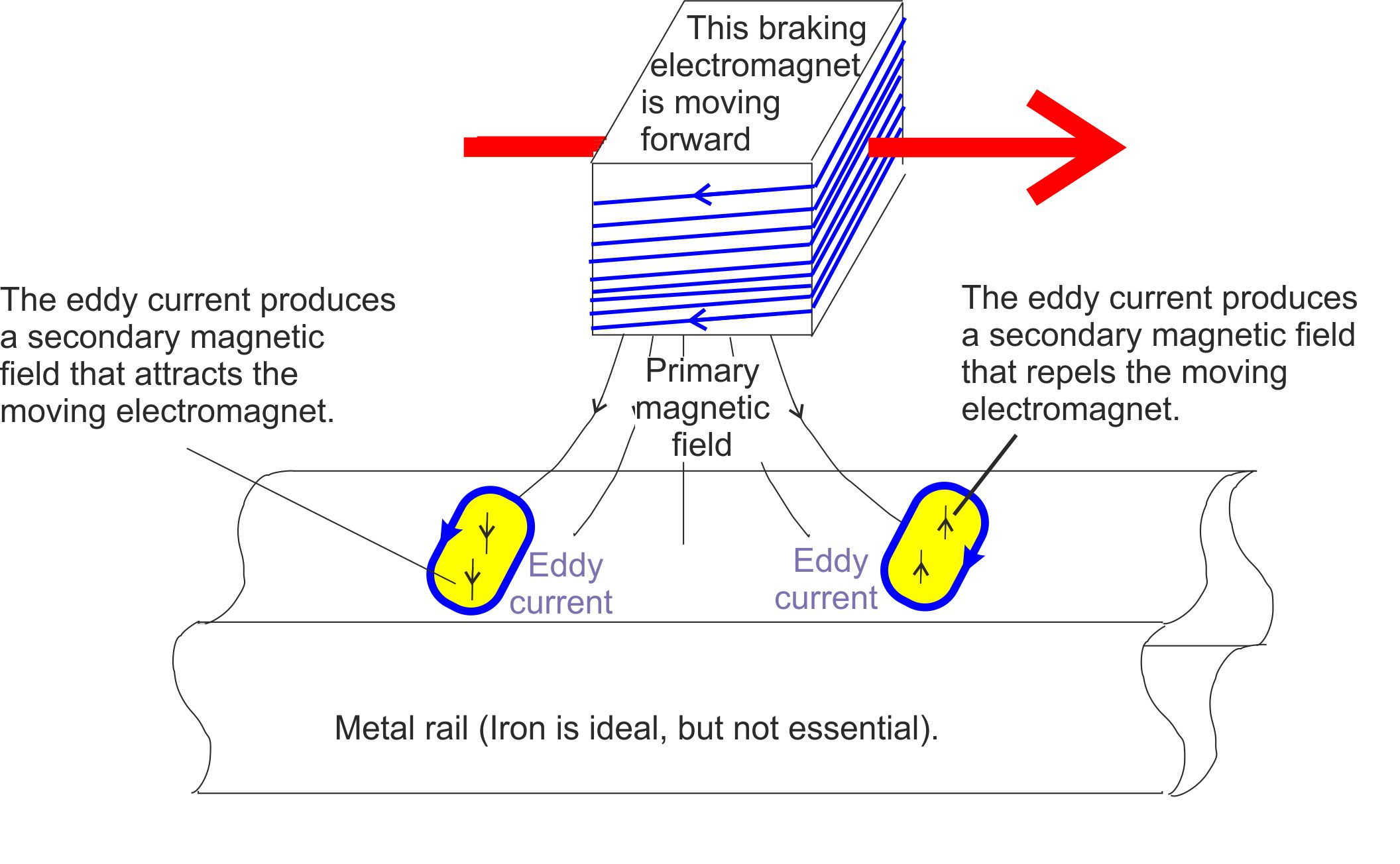
Figure 14.The swirling eddy currents can create secondary magnetic fields in any type of rail material that conducts electricity. But iron and steel amplify the magnetic fields because they are ferromagnetic materials.
Iron is approximately 50 times more effective than steel in enhancing the magnetic field strength. Consequently iron rails offer 50 times the braking power, compared with the same size of steel rail. Iron is also a better conductor of electricity, which further enhances its advantage over steel.
3.4 Converting ballast beds to concrete
When a train experiences a horizontal braking or accelerating force, the underlying sleepers experience an equal magnitude force in the opposite direction.
This will cause problems if the iron rails are laid on the ballasted tracks commonly used by local trains, but not on the concrete beds used by high speed trains. Fortunately, research provides evidence that ballast can be converted to concrete by the addition of a fluid form of mortar.
Modifying ballasted beds will add to the Iron Rail installation costs, but will pay off in the long term because of the lower maintenance costs of concrete beds.
[Reference: Experimental investigation on the application of quick-hardening mortar for converting railway ballasted track to concrete track on operating line, Lee et al., Constriction and Building Materials, vol 13, February 2017, p 154-162]
3.5 Keeping the iron rails clean
Ferromagnetic rubbish such as nuts, bolts and discarded steel cans will be attracted to the electromagnets and rails when they are magnetised. Even non-ferrous material such as twigs and plastic litter could cause problems in the restricted space between the base of the coils and the iron rails.
Two lines of defences are proposed.
(i) A modified form of cowcatcher could be fitted to the front of the train. This would scoop up debris and store it in a waste bin. The scoop would be shaped to take advantage of the Bernoulli Effect so that the debris was vacuumed off the track. It would also include a sequentially operating set of electromagnets behind the scoop that pulled ferromagnetic material towards the bin.
(ii) The front of the base of each Maglev coil or braking electromagnet could be fitted with a rubber scraper. These scrapers would also be shaped to take advantage of the Bernoulli Effect to suck up debris and rain water.
The coils could be connected to the axles by short stroke suspension units, with the inactive coils dropping down, but being kept just clear of the iron rails by rubber wheels attached to their base.
Likewise, the braking electromagnets could be fitted with small rubber wheels, so that they operated very closely to the underlying rails without the risk of smashing into them.
3.6 Pedestrian safety when crossing the rails in wet weather
The iron rails will become very slippery when they are wet. Either, their upper surface will need to be roughened, or a thin but durable high friction coating will need to be added to sections of the rails that are accessed by pedestrians and cyclists.
3.7 Hot Box Detectors
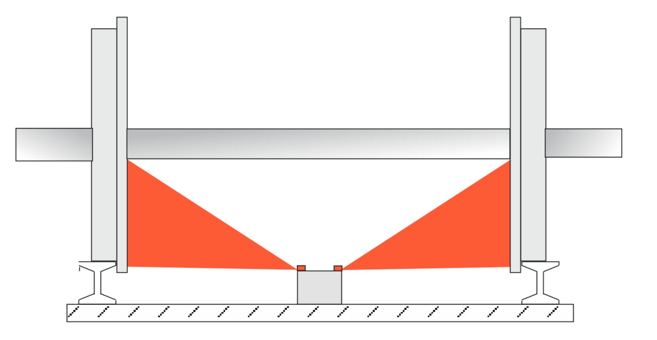
Figure 15. Hot box detectors are trackside systems that can pick up the infra-red radiation emitted by overheating bearings or wheels. In order to allow them to function correctly,
(i) There should be no braking electromagnets in the line of sight between the detectors and the infra-red heat source.
(ii) It may be necessary to replace trackside detectors with onboard detectors for Iron Rail Maglev trains.
3.8 Protecting Maglev trains from cross wind derailment
The upthrust on Maglev trains will reduce the down thrust on the train’s wheels/
Consequently the train will be more susceptible to being blown over or derailed in high cross winds. To some extent, negative feedback can offset this rotating couple because the upthrust falls if the armature is lifted higher above the track. [A wheel will be at imminent risk of derailment if it is lifted by 14 mm, so that its flange is at the same height as the topof the track.]
As a precaution, a counter-rotating couple should be applied to the train in high cross winds.
This could be done by reducing the current supplied to the windward side armatures and increasing the current supplied to the sheltered side armatures.
3.9 Tilting Maglev
When a train travels round a bend at high speed, the centrifugal forces involved can be unpleasant for the passengers and adversely affect the performance of the train.
Tilting trains that lean into the curve of the track at high speeds can reduce both of these problems and have become common on high speed trains in recent years. As with many things, they were invented in Britain, but developed commercially elsewhere.
Britain’s first tilting trains used hydraulic rams to achieve a tilt, but Iron Rail Maglev can achieve similar benefits using a far simpler mechanism.
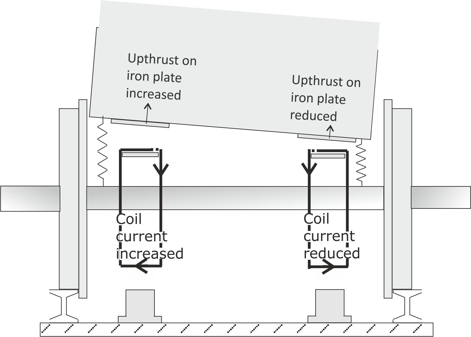
Fig .16 Several variations on this design are possible, offering different ride characteristics.
3.10 Latent Power Turbines for Maglev trains
Latent Power (LP) Turbines are power generators that use atmospheric heat as their fuel. They are discussed in detail on this linked page, with only a summary of their characteristics being provided here.
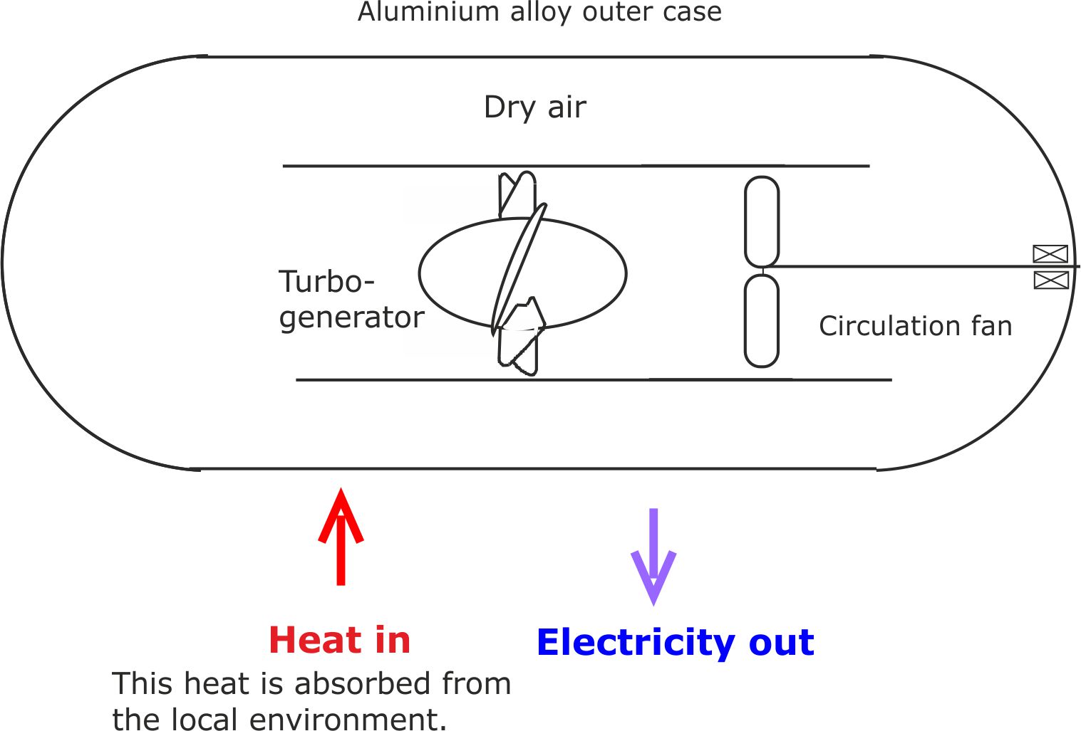
Fig 17. The outer case cools to several degrees below ambient during operation. So, to prevent ice forming on basic LP Turbines, their face temperature needs to be kept above freezing.
One way of doing this is to warm up the air inside the LP Turbine, for example, by burning a mixture of air and hydrogen.
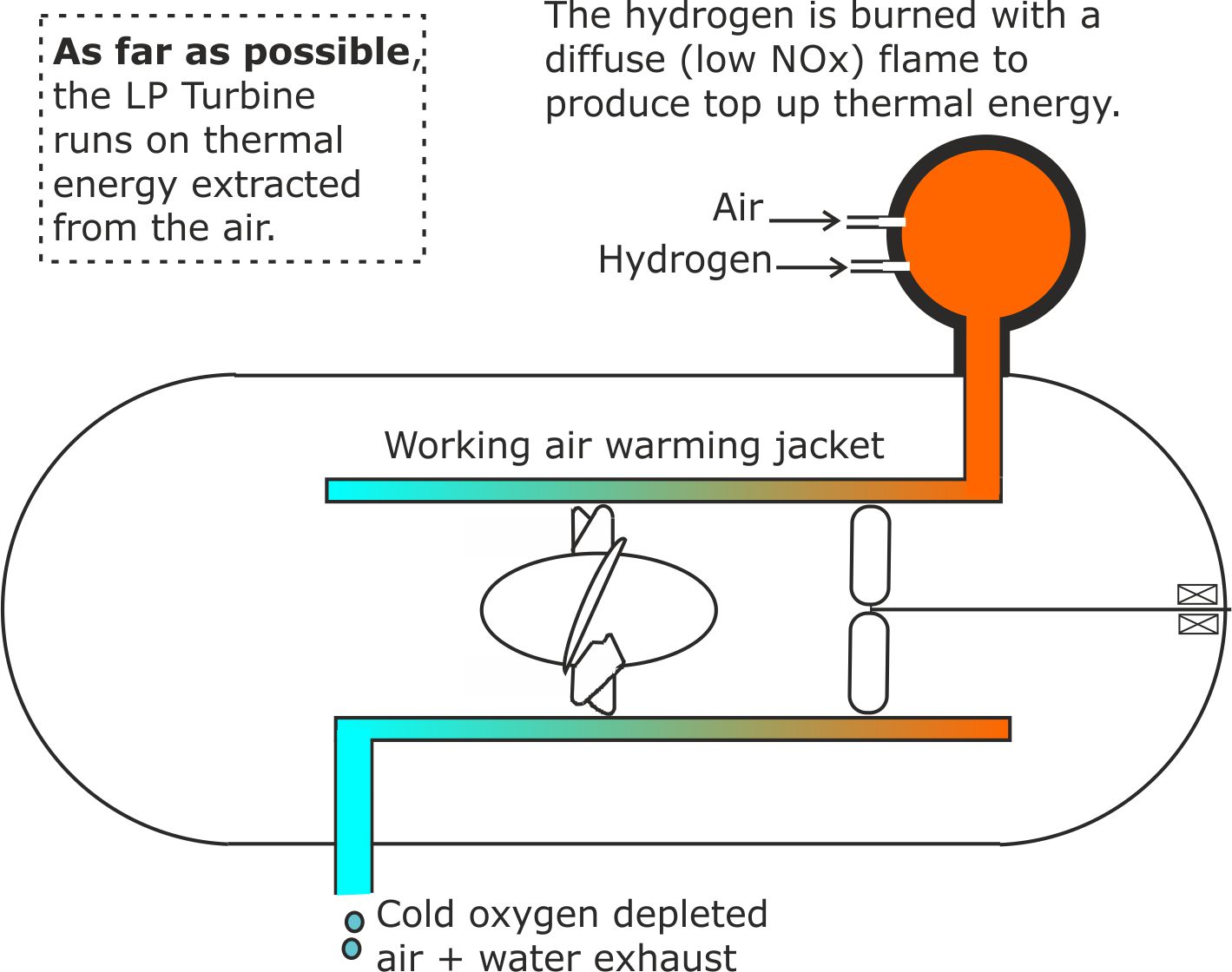
Fig 18. It is only necessary to burn sufficient hydrogen to keep the outer case above the freezing point of water.
LP Turbines could be used to power Iron Rail Maglev trains.
One of the design options is to use the formers on which the coils are wound as their outer casing.
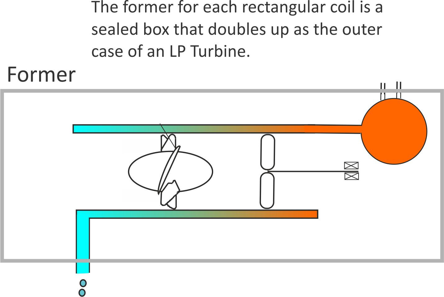
Fig 19. The I2R heat losses from the coils are recycled by the LP Turbine. In addition, heat can be drawn in from the environment, provided that the casing temperature remains above freezing.
This arrangement allows large electric currents to flow through the coils without them overheating.
3.11 Building split-level railways
The two Iron Rail innovations will allow trains to make steeper ascents and decants than friction grip limited trains. This will make it easier to build multi-level stations and overhead bypasses that allow fast trains to leapfrog over stations used by slower frequent stopping trains.
- 12. A ‘Dead man’s handle’ to improve cyber security
Centrally controlled traffic systems are vulnerable to cyber-attack.
The most basic form of protection is to make the system failsafe, so that movement comes to a halt if cyber criminals attempt to crash or derail a train.
All rolling stock units could be fitted with sensors that immediately apply the brakes if a large obstacle, such as another unit of rolling stock is closer than the headway (minimum time or distance gap) between trains.
This electronic ‘Dead man’s handle’ would also switch off the power supplies to the train control systems, to prevent further cyber mischief. Crucially, it would be a self contained unit that could not be accessed or checked remotely.
Similar self contained units would bring the train to a halt if it moved erratically and was in danger of being derailed.
In order to avoid collisions between units travelling towards each other along the same track, all rolling stock would continuously send out position information based on ‘milepost’ readings. Again, both the milestones and position transmitting systems would be a self contained unit that could not be hacked into from a distant location.
3.13 City trams
Trams are an environmentally friendly form of city transport but they slow don traffic flows and can cause traffic jams because of their poor acceleration and braking.
For example, local buses travelling at 20 mph will have a stopping distance of around 12 metres, whereas a tram travelling at the same speed will have a stopping distance of about 28 metres.]
Iron Rail technology would allow trams to match the performance of buses, with their superior brakes reducing tam accidents involving pedestrian, car and cyclists.
If they are hydrogen powered, the ugly and vulnerable overhead power lines could be dispensed with.
3.14 Some possible design variations
3.14.1 Vertical guideways for hyper-fast trains
In principle, there is a maximum speed that can be achieved by a Maglev train travelling above horizontal iron rails because as the propulsion power increases, so does the levitating force. So, if at a sufficiently high speed the train starts to move higher above the iron rails, a negative feedback effect will start to reduce the rate at which the traction power increases.
This limitation can be overcome by adding iron rail guideways on each side of the track to create a vertical rail version of the U shaped horizontal rails.
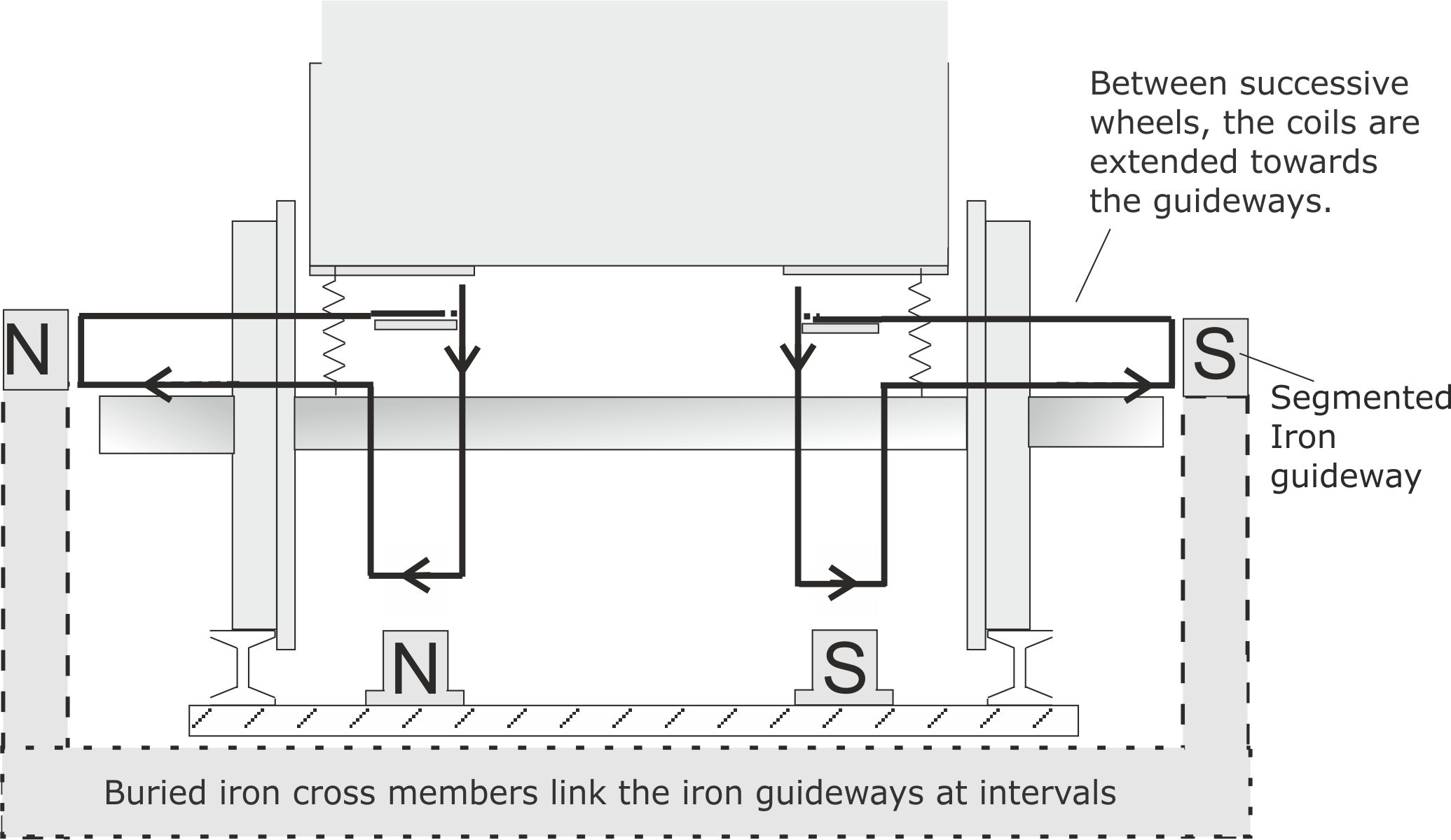
Fig 20. In addition to increasing the maximum traction force, the iron guideways increase transverse stability when travelling at high speed..
One potential problem with this design is that the coils will magnetise the steel rails, making them attractive to ferromagnetic debris. This effect can be neutralised by passing the currents through the coils in the opposite sense for successive trains travelling over the same rails.
Several other variations on the Iron Rail configuration are possible, offering different benefits. This will leave future generations of engineers with plenty of scope to modify the Iron Rail concept to meet specific demands.
3.14.2 Eddy currents produced by Maglev trains
As an armature moves forward, the magnetic field in the underlying rail first increases and then decreases. This means that each armature produces two unwanted eddy currents that oppose the motion producing them. The only way of minimising this opposition is to keep the number of armatures to a minimum, ideally having just two armatures X and Y that extend from the front of the train to the back.
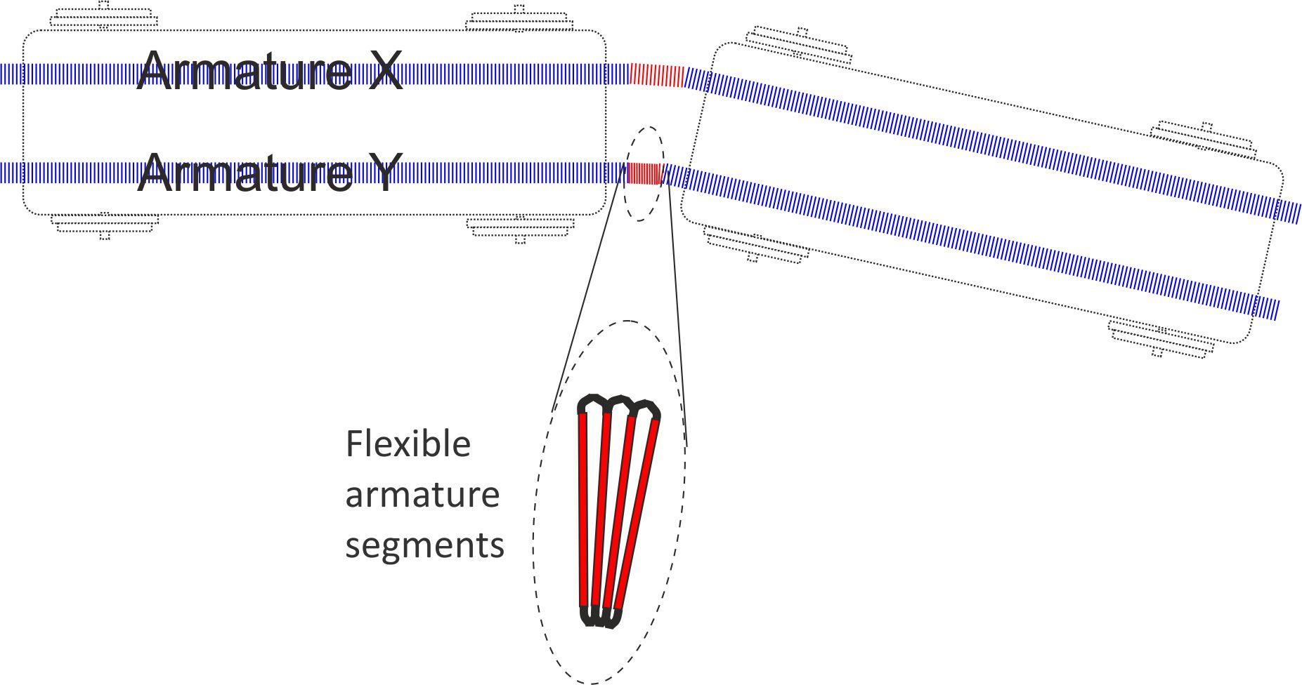
Figure 21. Two armatures X and Y need to flex so that the train can travel round curves.
3.14.3 Adding a Central Iron Rail
If long armatures are used to reduce the number of unwanted eddy currents, there will be very little room left for the installation of eddy current brakes. They could of course be installed inside the coils and only operate when the coils are switched off.
An alternative solution is to add a central iron rail, exclusively for the eddy current brakes to operate on.
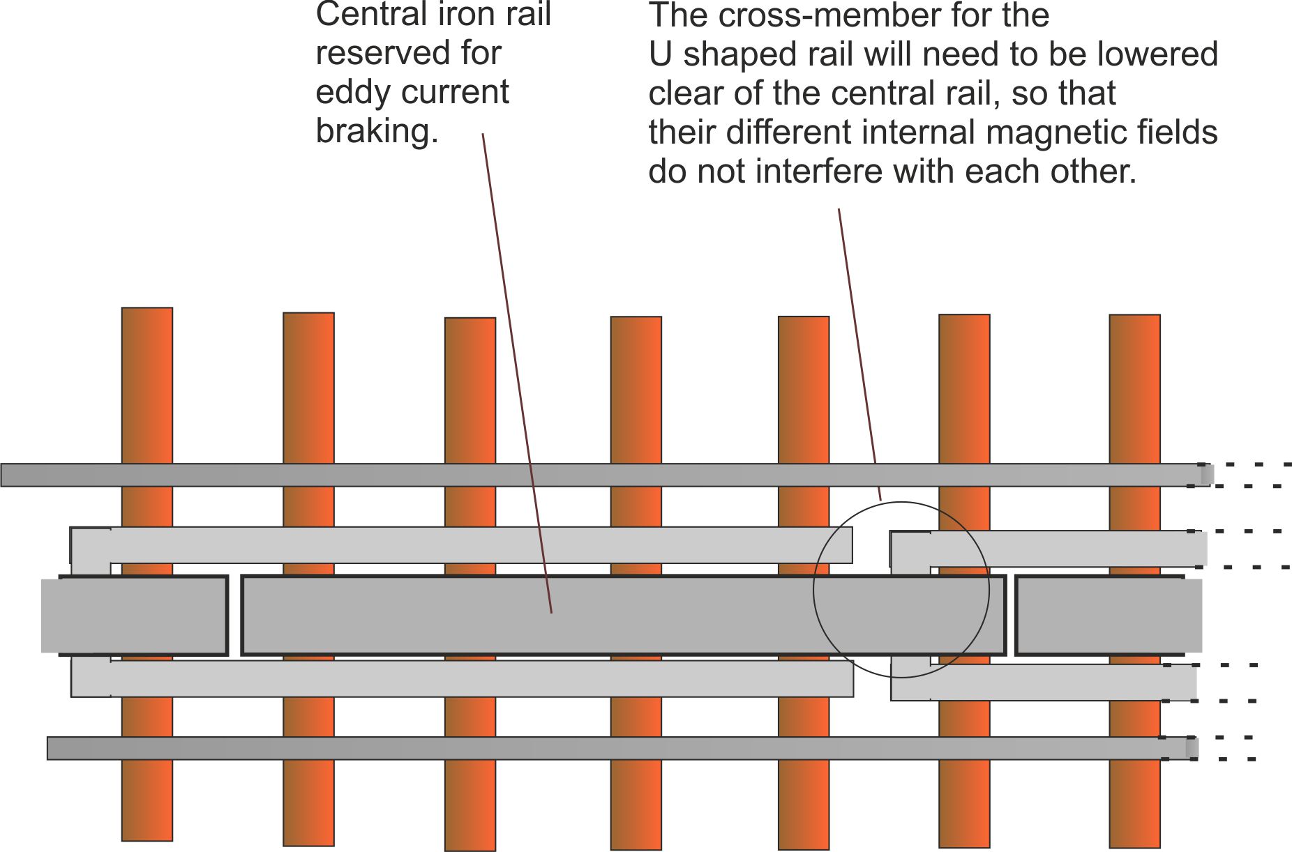
Figure 22. A small gap filled with non-ferrous material will need to be left between the cross member for the U rail and the overriding central rail.
3.15 ‘Maglev’ or ‘MagTrac’?
The primary aim of Iron Rail Maglev is to offer improved traction compared with friction grip trains. Accordingly, it may be more appropriate to refer to Innovation B as an ‘Iron Rail MagTrac’ system.
3.16 The origin of the Iron Rail Maglev concept Maglev systems.
Bill Courtney was inspired by Professor Laithwaite’s work, but his ‘light bulb moment’ came in the 1980s, while inventing a new type of power generating refrigerator for fighting climate change.
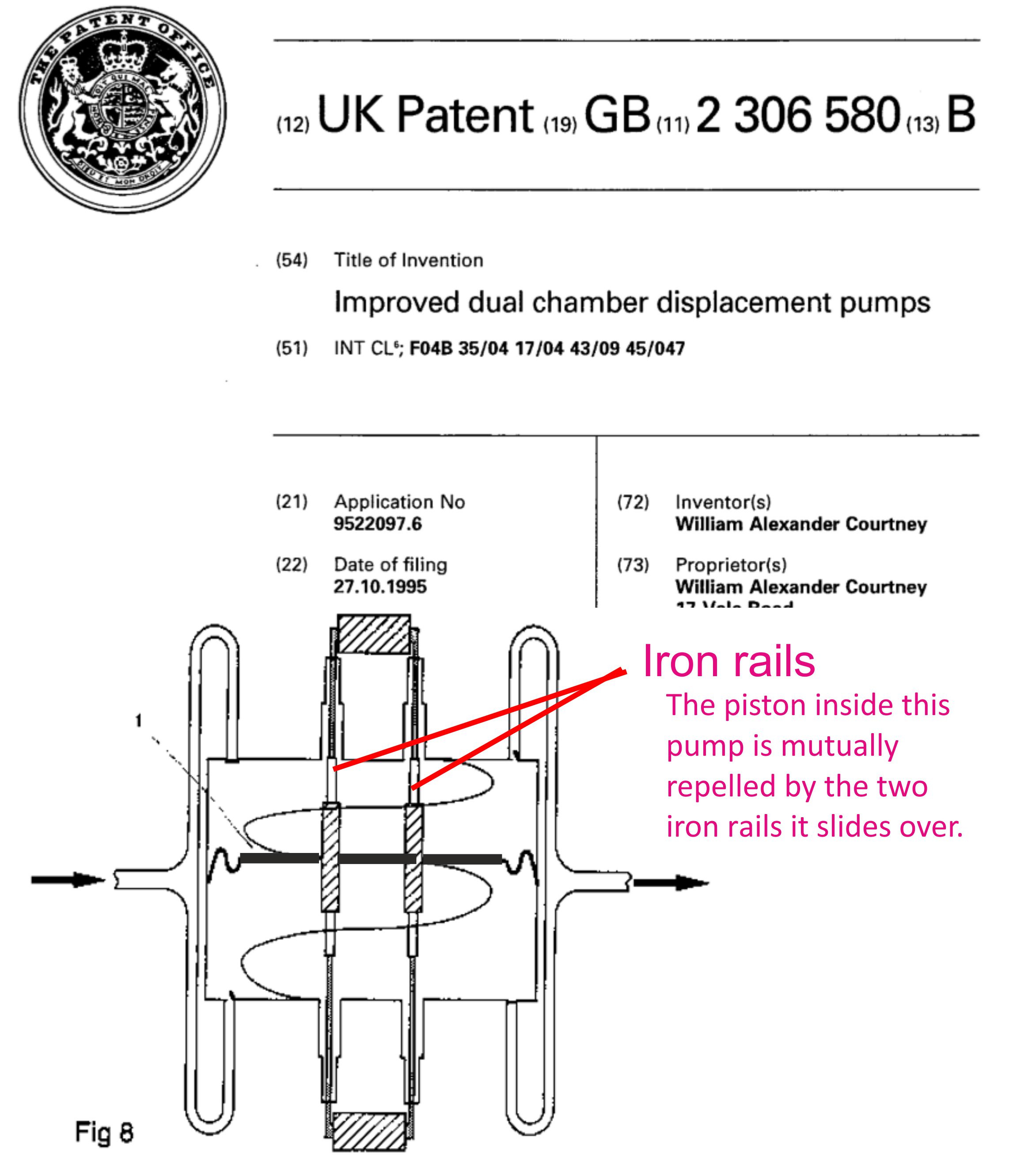
Figure 23. For further details of power generating refrigerators, visit this linked page.
CONNCLUDING NOTES
- Iron Rail eddy current brakes will allow freight trains to enjoy similar improved stopping distances to passenger trains.
- Iron Rail Maglev will allow freight trains to enjoy similar improved acceleration rates to passenger trains.
- Employing electromagnetic forces instead of friction for propulsion and braking will ‘future-proof’ railways, allowing the network to evolve by using the existing tracks in entirely new ways.
- Project cost estimates will be more reliable than for building new lines such as HS2 lite because no brand-new infrastructure will be required.
- The development of Latent Power Turbines in parallel with these innovations will allow Britain to become self-sufficient in making its own iron rails and massively reduce the fuel costs for future generations of trains.