1 Introduction
Motor vehicle suspension units provide passengers with a smooth, stable ride and make the steering easier to handle. Each unit has two components: a spring and a damper.

Figure 1. A simple car suspension unit.
The springs are compressed as the wheels travel over bumps. Then, as the springs expand, the dampers absorb energy, to prevent the vehicle bobbing up and down.
This damper action produces waste heat that has to be dissipated into the environment. Up to 5% of the vehicle fuel is used up by damper action, with the percentage increasing with vehicle size.
Our SALi suspension design is different. It converts energy mopped up by the dampers into electricity instead of wasting it. The electricity can be fed back into the battery, increasing the range of battery powered vehicles.
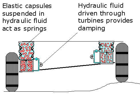
Figure 2. A SALi based suspension system that can generate electricity.
Modest savings on battery power create cumulative benefits: For the same travel range, battery weight, recharge times and battery purchase costs are all reduced.
If widely adapted in lithium-ion battery powered vehicles, this would lead to a useful drop in the market price of lithium and reduced demands on the power grid, when the batteries are being recharged.
We will describe our conventional SALi suspension designs, and then explain how they can be modified to produce electricity.
- The basic SALi suspension unit

Figure 3. The basic SALi suspension design integrates the spring and damper functions.
The elastomeric capsules (for example foam rubber or hollow rubber balls) can be compressed like springs. As the capsules change in size internal friction produces some damping. Additional damping is produced as the hydraulic fluid swirls round the shrinking/expanding capsules.
- Adding extra damping on the expansion stroke (Conventional design.)

Figure 4. The empty suspension unit.
The viscous damping grid can move up and down to act as a valve.
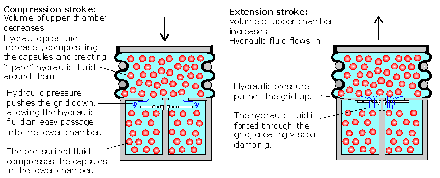
Figure 5. Hydraulic fluid can pass round the rim of the damping grid on the compression stroke, but is forced through holes in the grid on the expansion stroke.
Benefits of the conventional SALi suspension design:
Ø It does not require any precision made parts to be manufactured, so production costs are low.
Ø Low weight.
Ø The simple design reduces recycling costs at the end of the products working life.
(Rubber bellows suitable for research purposes are available from Firestone http://firestoneip.com/)
- The energy saving SALi suspension unit
Instead of forcing the hydraulic fluid through the holes in a grid, as shown in Figure 4, the holes are blanked off and the fluid returning to the upper chamber is diverted through a turbine.

Figure 6. The energy saving SALi suspension unit.
The turbine is coupled to a generator which produces electricity on the expansion stroke.
For small vehicles, the number of moving parts can be reduced by replacing the turbo-generator with an array of piezoelectric baffles.
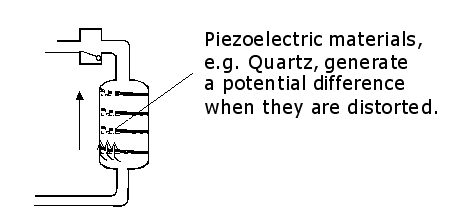
Figure 7. The Piezoelectric alternative for small vehicles.
- Fine tuning the suspension performance
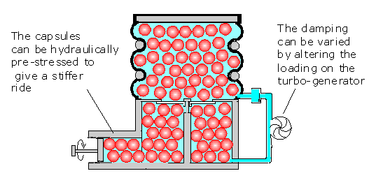
Figure 8. The design offers simple methods for altering the suspension stiffness and damping.
- Reducing the intrusive height of the suspension
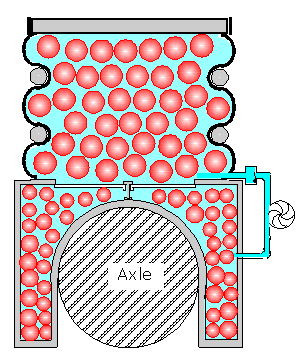
Figure 9. The designer has considerable freedom to choose the position and shape of the rigid walled chamber because the capsules are compressed indirectly by hydraulic pressure.
For example, the rigid chamber can be shaped around the axle, allowing virtually the whole height of the suspension unit above the axle to be compressed.
For the rear suspension, this creates extra space inside the boot or passenger compartment. At the front end, it creates extra space under the bonnet. Indirectly, this can improve pedestrian safety because it allows extra space for the bonnet to deform during a pedestrian impact.
- Improving the elastomeric capsule design
When cross sections through elastomeric foam capsules are examined using an electron microscope, a complex layer structure is revealed.
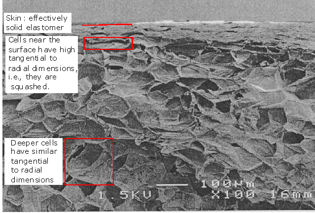
Figure 10. This electron micrograph shows the outer sections through an elastomeric foam capsule.
This structure can be used to advantage in SALi based suspension units because the stiffness of the capsules increases as they are compressed. Consequently, the unit gives a soft ride when travelling over moderate sized bumps, but stiffens up to cope with larger bumps.
The diagram below explains why stiffness increases with compression.
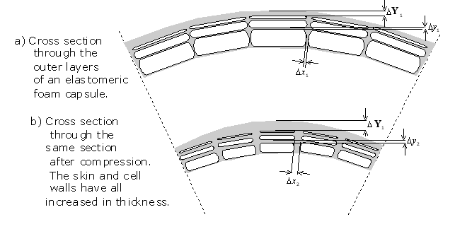
Figure 11. Compression increases elastomeric foam capsule stiffness because the gas inside the cells is compressible, but the solid elastomer (for practical purposes) is not. Consequently, the relative volume of the elastomer increases.
8 Preliminary investigations
Cardiff University School of Engineering
Student: Ben Robertson.
Supervisor: Dr. Huw Davies.

The project aim was to demonstrate that a simple SALi based suspension unit could work effectively.

Figure 12. The design investigated.

Figure 13. The prototype SALi suspension unit.

Figure14. Thin walled capsules consisting of individual cells cut from a sheet of polythene bubble packing were used. The capsules were uniformly stressed by the surrounding hydraulic fluid, so there was no risk of them popping.

Figure 15. The unit was subjected to 1 Hz vibrations.

Figure 16. (Originally Fig. 2.in the student report.)
These results show that:
(i) The prototype unit produces repeatable performance over a number of oscillations.
(ii) Damping is produced as the rubber bellows is deformed and the hydraulic fluid swirls around the elastomeric capsules. The amount of damping can be calculated from the area of the closed loops.
Figures 13-16 above © Huw Davies & Ben Robertson, Cardiff University
