Obtaining these core characteristics is a challenge for engineers
Each SALi formulation has its own unique set of core characteristics, depending on the type of capsule and matrix fluid used.
For example, cheap expanded polystyrene beads can be used in SALi for car bumpers, but good quality rubber beads are required for vehicle suspension systems.
|
SALi formulations offer more viscous damping than foam pads made from the same material as the SALi capsules.
For the end user this means improved impact protection. But for the product designer, viscosity adds complexity because viscous damping increases with the rare at which the capsules are compressed. (i.e., viscous damping increases with bulk strain rate.)
So, to assist product designers, each SALi formulation requires a family of core characteristics relating to different strain rates.
The following notes are written for anyone wishing to work with Bill Courtenay, developing SALi Technology.
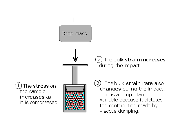
An “obvious” way of determining core characteristics is to carry out impact tests on samples of SALi trapped inside a piston and cylinder container. However, this type of test is not quite as simple as it looks.
Here’s why:

Figure 2. The three important variables change simultaneously during each test. Ideally, to produce usable characteristics, the bulk strain rate should remain fixed, while the relationship between stress and strain is investigated.
Here are two proposals for keeping the strain rate constant
Method 1.
The sample is compressed very rapidly, to simulate an impact, but the piston moves down at a steady rate. This requires a complicated and expensive test rig.
Method 2
Accept that impact experiments involve three simultaneously changing variables and include instrumentation to measure them.
Then process the data from a series of tests to generate a family of constant strain rate curves.
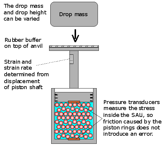
The modified piston and cylinder for this method is shown below.

Figure 3. A piston and cylinder arrangement suitable for the measurement of stress, strain and strain rates.
Design notes:
(i) The three variables, dynamic stress, bulk strain and bulk strain rate are recorded during each impact.
(ii) The pressure transducer attached to the piston crown provides data about the stresses on the front face of a SALi based impact absorber. This is required for example, for designing soft car bumpers that minimise damage to pedestrians in lower leg impacts.
(iii) The pressure transducer attached to the base of the cylinder provides data about the stresses on the back face of a SALi based impact absorber. In the car bumper example, this relates to protection offered to the body of the vehicle and its occupants in any front bumper collision.
(iv) Ringing vibrations produced as the drop mass hits the anvil can be overcome by placing a rubber buffer on top of the anvil.
(v) The drop mass will ricochet off the anvil, so the impact velocity of the drop mass does not provide any useful information about piston movement.
(vi) Fluid stresses are measured inside the cell, so friction between the piston rings and the side walls does not introduce an error.
(vii) A similar argument applies to the rubber buffer: because the stresses are measured inside the cell, the characteristics of the rubber buffer are irrelevant.
(viii) The piston and anvil should have a low mass to minimise the zero loading error.
(ix) The different SALi formulations will need to be subjected to a wide range of impact velocities and energies.
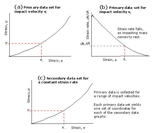
(x) This primary impact data will then have to be cross referenced to produce families of secondary data, showing dynamic stress-strain relationships at different strain rates.

Figure 4. These sketch graphs indicate how the primary data can be cross referenced to produce stress-strain curves at different strain rates.
Conclusion
A single SALi formulation will produce a whole family of dynamic stress-strain curves depending on the impact conditions.
To date, only one attempt to measure SALi core characteristics has been published. [11, 14.] Unfortunately the authors failed to recognise the importance of separating out the three key variables. The results were limited to the primary data, as in sketch graph (a) above. As a substitute for different strain rates, the results were presented for different drop mass impact velocities. (Which are meaningless; see point (v) above.) The authors were also distracted by trying to take into account the characteristics of the rubber buffer. Again, this is irrelevant if the experimental design is correct and all stress measurements are made inside the test cell.
These published results have no scientific value. The SALi Technology inventor, Bill Courtney, refused to add his name to the papers. He also objected to their publication because they wilfully misled the international research community.
For details of this misleading research please click.
Alternative apparatus: Split Hopkinson pressure bar
In 2003, Dr John Harrigan, then at the University of Manchester Institute for Science and Technology suggested the construction of a small SALi retention cell inserted into a Split Hopkinson pressure bar. He also suggested that the bar should be made from polycarbonate plastic, to match with the high compressibility of SALi. Harrigan’s suggestions look promising and are worth pursuing. There could be a PhD thesis in this for somebody!
For basic information about Split Hopkinson pressure bars visit
http://en.wikipedia.org/wiki/Split-Hopkinson_pressure_bar
References
The following reference numbers are taken from our What is Shock Absorbing Liquid (SALi) Technology? web page.
11 S O. Oyadiji et. al., University of Manchester, Core property characterization for a shock absorbing composite, SAVIAC 75th Symposium, 17-22 October 2004.
14 G. Georgiades et. al., University of Manchester, Characterization of the Core Properties of a Shock Absorbing Composite, Journal of Engineering Materials and Technology, ASME, October 2007, Vol. 129, pages 497-504.

