1 Brief summary of current results
This is a photograph of the closed loop system we are using for our research.
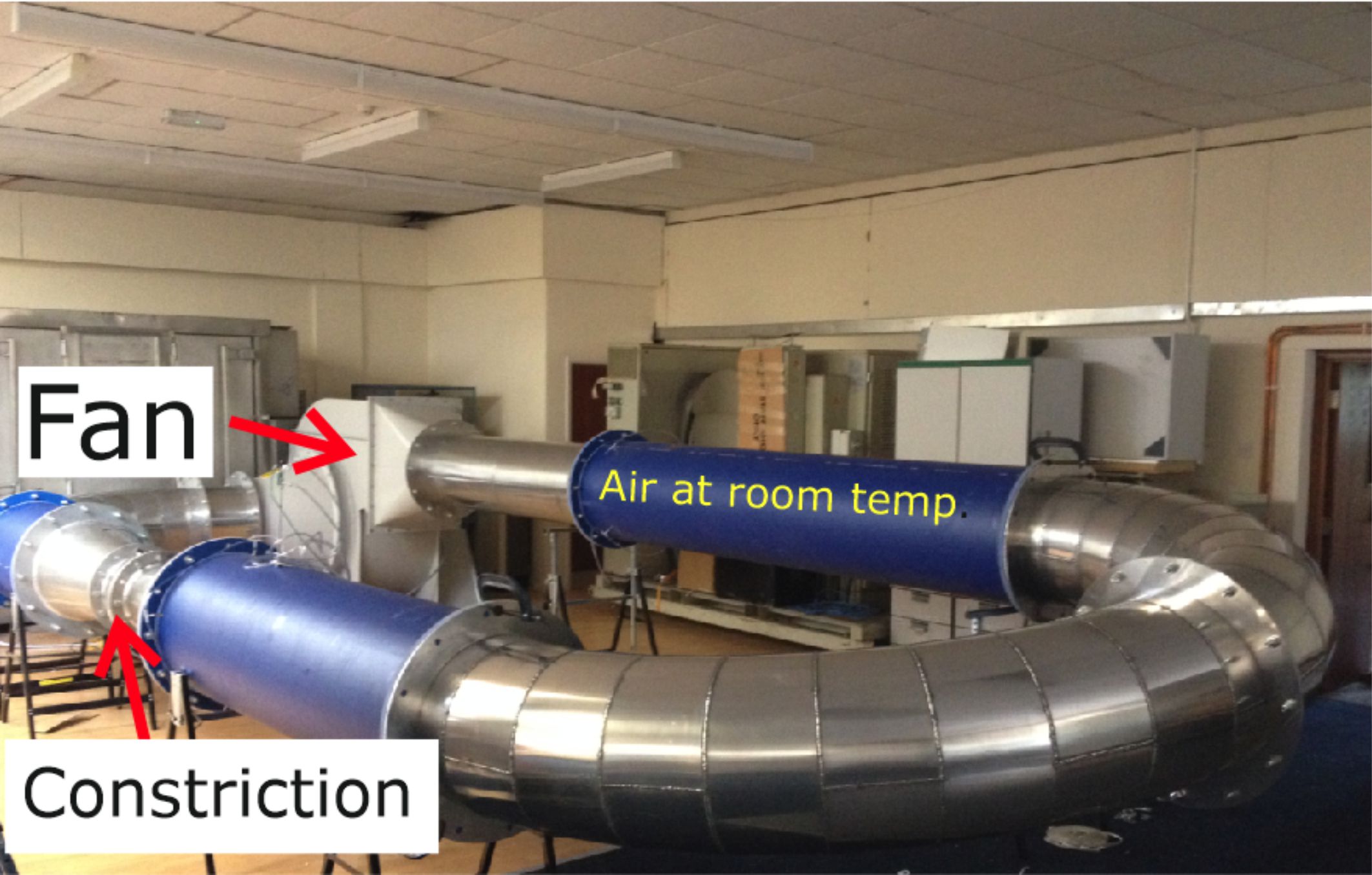
Figure 1. Our original plan was to use metal piping for the complete loop. But to save on costs, some sections were made from blue plastic mains water pipes.
Here is a descriptive summary of our results:
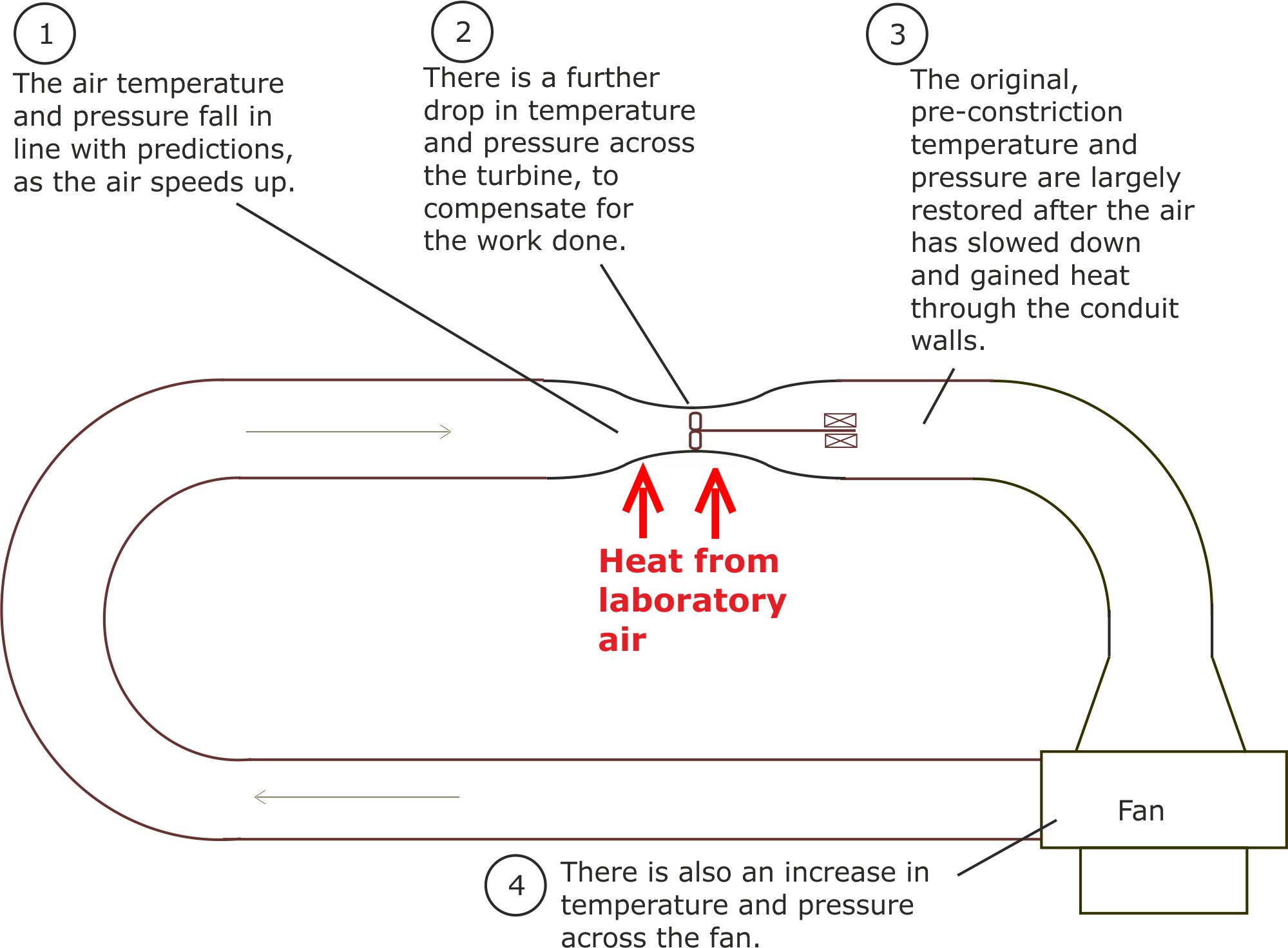
Figure 2. The changes in temperature and pressure around the loop were in line with our predictions.
In order to check that our experimental results were not a fluke, we repeated the experiments over a number of days using different fan speeds.
We also built an environmental chamber around the converging-diverging zone and used an electrical heating system to alter the 'laboratory' air temperature. The results were always in line with our expectations.
[Final Report for Innovate UK (Technology Strategy Board) Project 131512.]
However, we did not have sufficient funds to commission the design and construction of a bespoke turbine. Instead, we had to improvise, using a cannibalised set of air conditioning unit fan blades. These had entirely the wrong shape, producing a lot of turbulence and preventing a net output of power.
The quantitative results are currently being written up for journal publication.
2 Formulae linking electrical power input and output
To simplify the maths, we will assume that the working air acts as an incompressible fluid.
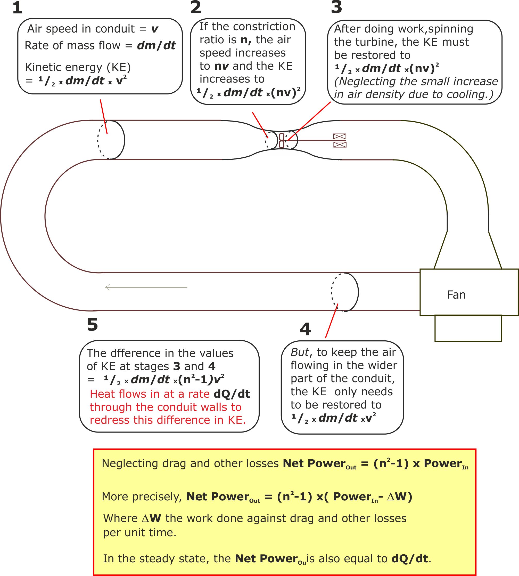
Figure 3.
3 LP Turbines and the Carnot equation
Latent Power Turbines have two novel design features that give them surprising properties.
(i) They incorporate a thermal feedback loop.
(ii) They can run 'cold' at a lower temperature than the laboratory air.
Figure 3 below explains how the internal heat engine can have a very low Carnot efficiency, while still allowing the LP Turbine as a closed loop engine to have a high thermal efficiency.
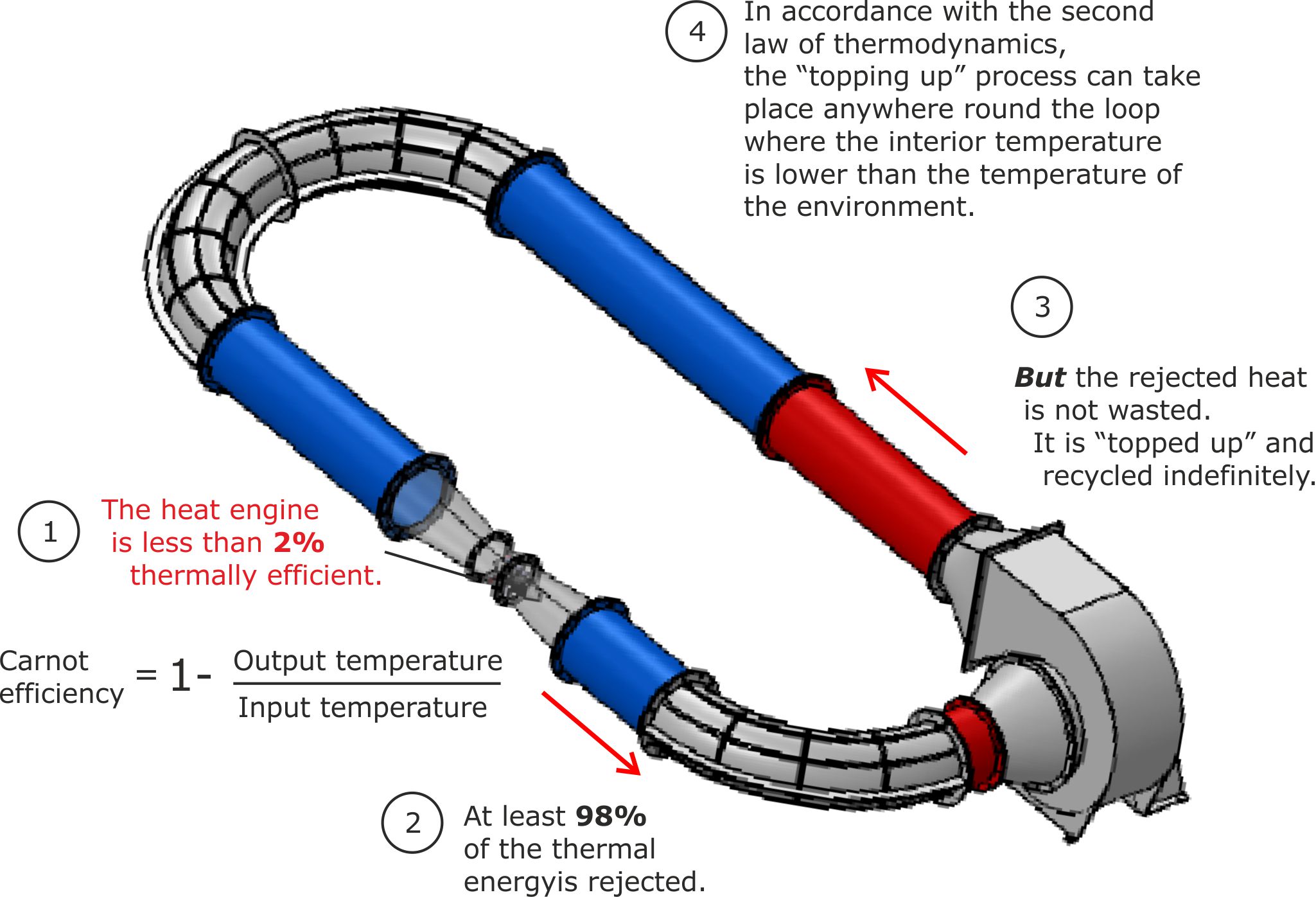
Figure 4. Thermal feedback explains the apparent paradox between low heat engine and high LP Turbine efficiencies.
4 Treating an LP Turbine as a pair of nested black boxes
The black box approach provides another way of understanding how a Latent Power Turbine can appear to be 100% thermally efficient, without violating the laws of thermodynamics.
Before examining the 'black boxes' we need to write a few notes about the first and second laws of thermodynamics.
The first law Essentially this tells us that energy cannot be created or destroyed. It can only change from one form to another.
The second law Textbooks and thermodynamics experts can write the second law in a number of different ways. But all of them encapsulate the following truths about nature:
(i) An engine that converts heat into another form of energy can never be 100% efficient. Some heat must always be rejected into a cold reservoir at a lower temperature than it entered the heat engine.
(ii) Heat can only flow from a warmer body to a colder body.
4.1 The internal black box
This is a heat engine.

Figure 5. The internal black box is a heat engine that must be consistent with the second law of thermodynamics. That is, it must posse a hot reservoir and a cold reservoir with some of the heat being rejected into the cold reservoir.
4.2 The external black box
This represents a closed loop mechanical engine that performs the following functions:
(i) It speeds up the working fluid (room temperature air) by passing it through a converging section of the conduit. In order to be consistent with the first law, the air temperature must fall as its kinetic energy increases.
(ii) It recycles the rejected heat.
(iii) It takes advantage of the second law because anywhere round the loop where the working fluid is cooler than room temperature, it can draw in heat from the warmer room.
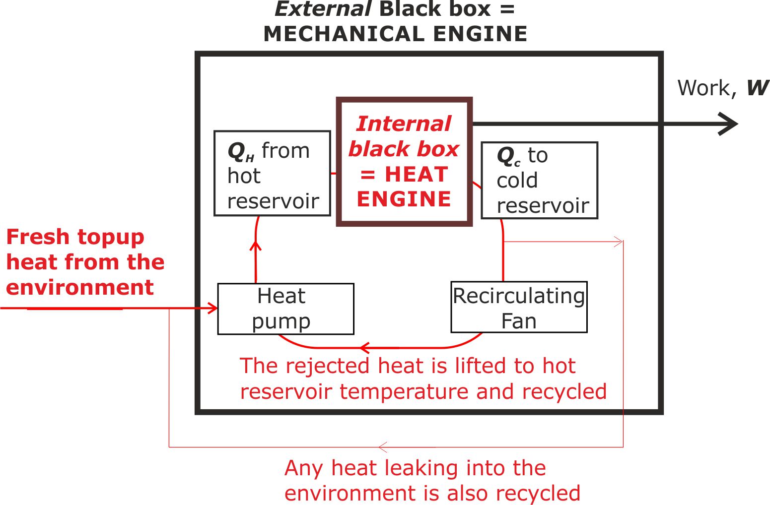
Figure 6. The external black box is a heat recycling system. It can only recycle the heat and add extra 'top-up heat' because a converging-diverging system is used to ensure that the hot reservoir is always at a lower temperature than the surrounding laboratory air.
Key points to note:
(i) This representation is only valid because the hot reservoir is below laboratory temperature, with the cold reservoir being at an even lower temperature.
(ii) A superficial interpretation suggests that this is a system the violates the laws of thermodynamics by reducing entropy. This superficial interpretation is not valid because the external black box is only one part of a larger system that must include the final destination as very low grade heat that the work output is destined to reach.
Ultimately, when we include the environment in the bigger system, then over time, the entropy of the system increases.
5 A comparison between Latent Power Turbines and heat pump systems
At first glance, both LP Turbines and heat pumps appear to violate the laws of thermodynamics because they extract heat from cold air. But on closer examination, both obey the laws.
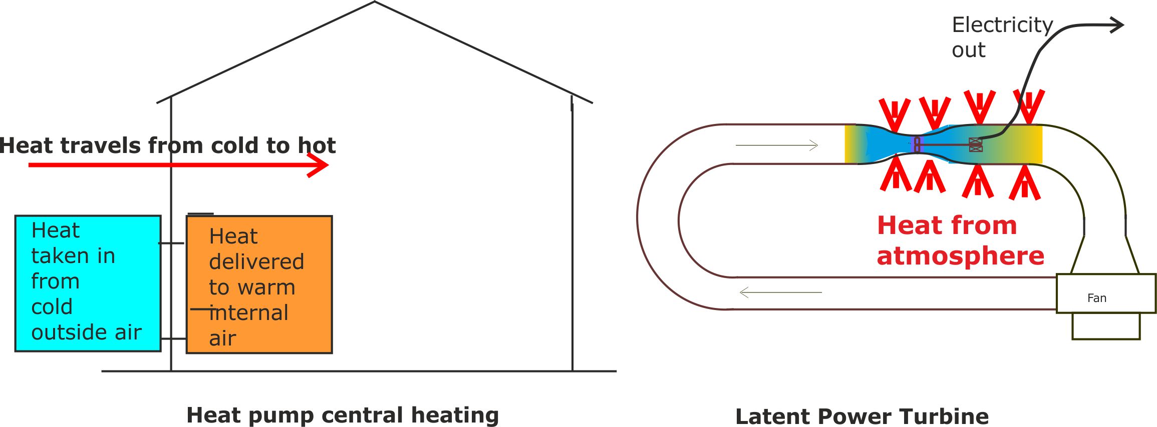
Figure 7. Heat pumps and LP Turbines both appear to defy the laws of thermodynamics until you look at them closely.
Heat pump based central heating systems are replacing traditional gas fired boiler systems because of their lower carbon footprint [https://en.wikipedia.org/wiki/Air_source_heat_pumps]. They absorb heat at a low temperature from the cold outside air; pump it to a higher temperature, and then release it inside the warm building.
This appears to defy the laws of thermodynamics because heat naturally flows from hot to cold. To get round the law without violating it, they employ a refrigerant fluid that changes phase as it is pumped round the system. In the cold part of the system outside the building, the fluid is forced to absorb latent heat when it evaporates at low pressure. This causes the fluid temperature to fall below the outside air temperature. Heat can then flow from the cold outside air into the even colder fluid vapour.
The reverse then happens inside the building. The vapour is compressed so that it heats up and releases latent heat as it turns back into a liquid. So, provided the heated liquid is at a higher temperature than the air inside the building, heat can then flow from the liquid to the internal atmospheric air. Typically, 3kW of heat can be pumped into a building by expending 1 kW of electricity operating the pump.
Our Mk 1 Latent Power Turbine employed air mixed with water which acted in a similar manner to a refrigerant fluid. That is, it changed from vapour to liquid as it passed through the turbine, releasing latent heat to power the turbine. The system worked as we predicted but we were worried that flying water droplets might damage the spinning turbine blades. In pondering over this problem we realised that we had over-engineered the design in our attempt to mimic the success of heat pump systems. In fact, design differences compared with heat pumps meant that the release of latent heat was an unnecessary complication.
For our Mk 2 Latent Power Turbine we use dry air as the working fluid and still obtained results in line with our predictions. By this time we had registered ‘Latent Power Turbines Ltd’ as our company name. So we decided to stick with the name, even though latent heat no longer featured in the design.
What we can learn from heat pumps
Heat pumps include a defrosting cycle, enabling them to work efficiently, even in the UKs cool damp climate. This is reassuring because it implies that LP Turbines will also operate reliably in damp winter conditions without freezing up.
6 Entropy and Latent Power Turbines
An analogy with plants
In order for plants to grow they must capture carbon from randomly moving carbon dioxide molecules in the atmosphere and convert this into a far more ordered form of carbon inside the plants. This produces a localised and temporary reduction in entropy. But when the plant dies and rots away or is burned, the cellular material of the plant breaks down and the carbon reverts to a less ordered, higher entropy form.
Likewise with Latent Power Turbines; they produce a temporary localised reduction in entropy when they convert low grade heat into a more useful form of energy. But, whatever we do with that energy, it will always eventually revert back to low grade heat.
Neither growing plants nor running LP Turbines with enable us to avert the eventual heat death of the universe!
7 An enthalpy-pressure chart for LP Turbines
A thermodynamic chart that faithfully describes a working LP Turbine would be rather cumbersome and impossible to verify by experiment because in the vicinity of the heat engine, several thermodynamic processes overlap.
To simplify the analysis we will notionally lag the converging-diverging section so that heat from the environment is forced to enter the system in the following parallel sided section of the duct.

Figure 8. All parts drawn in blue are lagged so that heat only enters the loop after the engine has done external work.
Lagging the parts offers no practical benefits but is convenient for separating out the heat flow processes in a manner that can be experimentally verified.

Figure 9. Enthalpy – Pressure chart with heat flow processes separated out.
For ease of explanation, we have assumed that the temperature at B will be ambient. It is possible that this temperature will need to be slightly below ambient for the temperature gradient across the bare metal walls to draw in replacement heat. This simplification does not affect the shape of the chart.
A At A the fan does work on the air so the air warms to above ambient temperature. Prior to A, the air inside the conduit is assumed to be at ambient temperature.
B The air starts to cool as soon as it enters the throttling throat. B is the point at which the temperature has fallen back to ambient.
C This is the point immediately after the air has transited the turbine. The air has cooled thanks to throttling and also because the turbine has done work, powering the generator. There has also been some heating due to friction as the conduit tapers and as the air passes through the narrow gaps between the turbine blades.
C’ Is the lowest point on the enthalpy-pressure chart that would have been reached if there had been no heating and corresponding pressure increase due to friction. ( Enthalpy-Pressure chart only.)
D At the end of the lagged throttling constriction the air temperature is below ambient because the air has done net work driving the turbine.
E Heat flows in through the conduit walls so that (in this ideal analysis) the air temperature has been restored to ambient. DH is the net heat extracted from the environment during the cycle.
Finding out more
1 Details of the many ways in which LP Turbines could change our society
3 Using Latent Power Turbines to solve our water shortage problems
4 Using Latent Power Turbines to defeat terrorism
References
These are our original research reports for Innovate UK (Technology Strategy Board) who part funded the Latent Power Turbine research
2 Courtney, W. A. and West, R, Latent Power Turbines Ltd, Technical report for Innovate UK (TSB) Project. Number 131512-23, (April 2015).
